Dissolution Technology Development of E-Glass Fiber for Recycling Waste of Glass Fiber Reinforced Polymer
Article information
Abstract
Recently, E-glass fiber is the one of most widely used ceramic fiber for aerospace fields. Recycling technology for waste of wind power blades is arising issue for reasons of low manageability and high cost of wastes. Though glass fiber is perfectly dissolved in hydrofluoric acid, low cost for recycling and harmless to human is important for recycling of blades. Chemically melted glass fiber will be used as different purpose like accelerator of hardening for shotcrete. In this study, dissolution process of glass fiber is tested in NaOH solution at low temperatures. In addition, difference in diameter reduction of glass fiber is observed by various alkali concentration and reaction times, treatment temperatures using FE-SEM.
1. Introduction
Fiber-reinforced Plastic (FRP) is one of the most widely used materials in industry because of its excellent corrosion resistance and high specific strength compared to metallic materials.1) Among various types of FRP, Glass Fiber-reinforced Polymer (GFRP) is reinforced with E-glass fibers, and provides excellent mechanical and anti-chemical properties. For these reasons, GFRP is widely used in aerospace applications and as the material for wind turbine blades.2) Notably, as wind power generation is gaining attention as an alternative energy source to reduce atmospheric pollution, including fine dust, there is a growing trend toward larger and larger wind turbine blades.
Despite its excellent mechanical properties and large market share, however, GFRP still has a disadvantage, in that it is not easy to recycle. When GFRP is deemed to be no longer useful for its intended purpose, the materials are disposed of, including through reclamation, but this approach is not recommended due to cost concerns.2) Also, given that nearly 75% of industrial GFRP products are thermoset polymer composites, their recycling is even more difficult. Having said that, wind turbine blades, which are mainly composed of GFRP, have a short service life of around 20 years and thus must be subject to appropriate waste treatment.3) Against this backdrop, there is a growing need to develop GFRP recycling technology. To this end, it is necessary to implement recycling technology for epoxy and E-glass fibers first.
E-glass fibers are widely used in various applications due to their excellent mechanical strength and electrical and chemical properties, along with high heat resistance. With these advantages, E-glass fibers currently account for over 90% of all reinforcing materials available in the fiber-reinforced composite market, and their market is expected to reach an estimated KRW 120 trillion worldwide by 2020.2,4,5) E-glass fibers are largely composed of 54.3% of SiO2, 15% of Al2O3, and 17.3% of CaO and similar to silicate glass in terms of composition.
The most effective way to decompose E-glass fibers is using hydrofluoric acid, but its toxicity and harmfulness to the human body make this approach less desirable for commercial use. Alternatively, it has been found that strong alkalis, such as NaOH, are capable of decomposing E-glass fibers to the same extent as can be achieved by hydrofluoric acid.5–7) Also, replacing hydrofluoric acid with NaOH makes the decomposing process eco-friendlier, less harmful to the human body, and easier to control. For that reason, decomposing silicate glass using alkaline aqueous solutions has been widely discussed in a large number of studies.8–10) Simply put, when heat treated with Na-based compounds, E-glass fibers can be recycled.
The chemical decomposition of glass has long been studied, and can be largely classified into two major approaches. The first approach is leaching, an ion exchange process, where molten glass components are removed. This reaction occurs between protons in an aqueous solution and alkalis in glass, thus leaving more or fewer silicate structures. The second approach is etching, where glass networks are destroyed in an alkaline aqueous solution. This process dissolves all glass components into the aqueous solution and thus is time-dependent. Here, it is noted that the reaction between alkalis and glass is significantly affected by the composition of the concerned glass and decomposition conditions.8,11)
The present study intended to determine the appropriate conditions for the recycling of E-glass fibers used in GFRP. To this end, E-glass fibers without epoxy were dissolved into an alkaline aqueous solution and examined. E-glass fibers were treated under various conditions by adjusting the concentration of alkaline aqueous solutions, reaction time, and reaction temperature, and the variation in their diameter was observed. Also, how the slope of graphs that represent the reduction in fiber diameter changed for various formulations of alkaline aqueous solutions under severe conditions was investigated.
2. Experimental Procedures
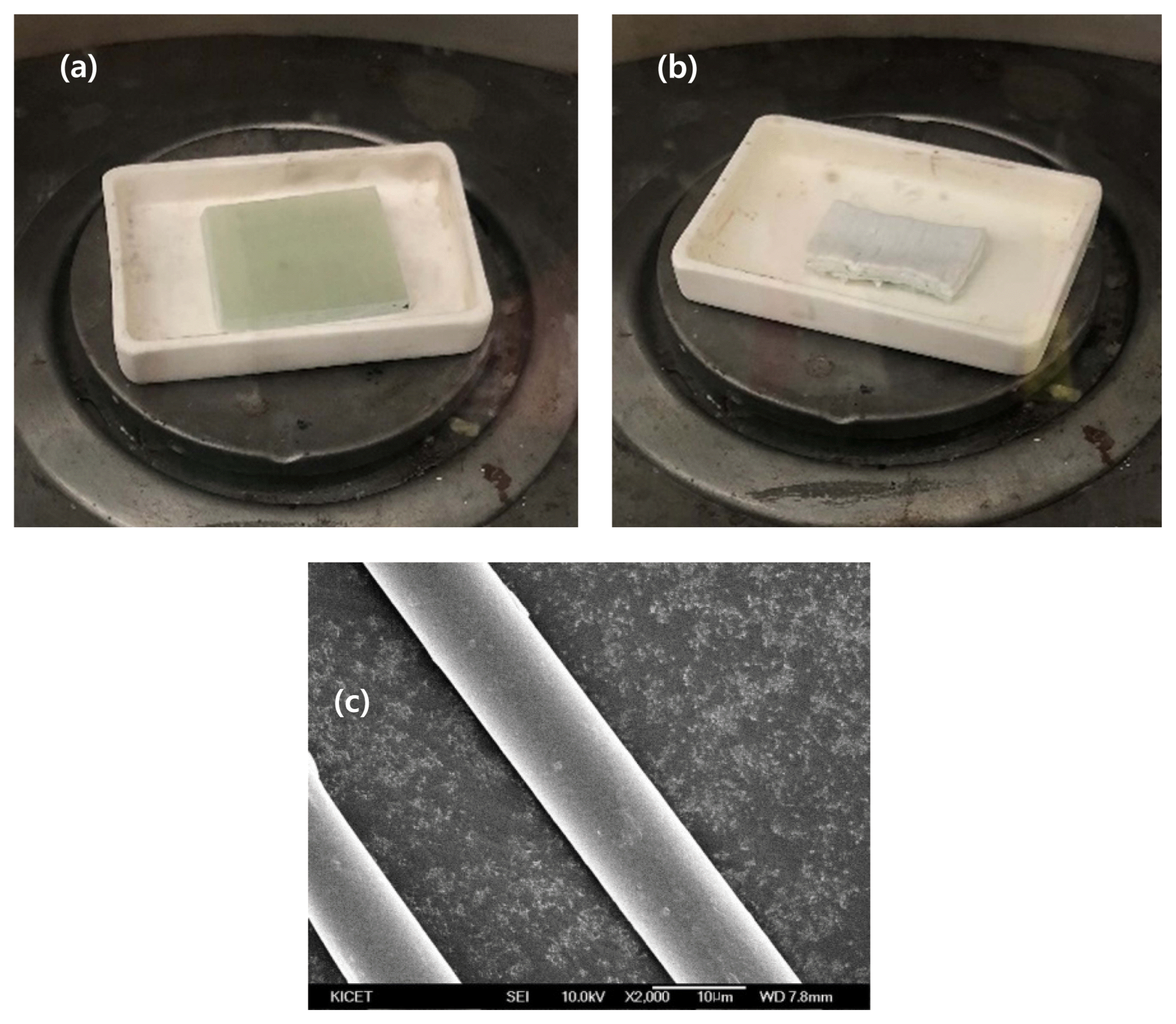
To obtain E-glass fibers, waste GFRP provided from Hangwon Wind Farm on Jeju Island was treated in an attempt to burn out its epoxy components. More specifically, waste GFRP was subject to heat-treatment at 900°C at atmospheric pressure and in the air atmosphere for 24 h. As a result, its epoxy components were removed, and E-glass fiber samples were obtained, as shown in Fig. 1. During the heat treatment, the weight of the waste GFRP decreased from 6.72 g to 4.95 g, implying that the amount of epoxy burnt out was 26.3% of its initial weight.
The obtained E-glass fibers were dissolved in NaOH pellet (98% purity, Sigma-Aldrich) while varying the solution concentration from 3 to 9 mol, treatment temperature from 75 to 95°C, and reaction time from 1 to 5 h. As such, the effect of varying decomposition conditions was examined. To keep the solution temperature constant during the dissolution process, a heating mantle stirring system was established and used. Every time the intended reaction time was reached, the E-glass fiber samples were collected from the solution and neutralized with a dilute hydrochloric acid solution (37%, Sigma-Aldrich) and distilled water. More specifically, the samples were immersed in a dilute hydrochloric acid solution for 15 min and washed twice with distilled water. Their pH was measured to be 7–8. After this cleaning and neutralizing process, the E-glass fiber samples were dried for one hour in an oven at 100°C. A Field-emission Scanning Electron Microscope (FE-SEM) was used to observe the change in the diameter of these E-glass fibers dissolved in alkaline aqueous solutions.
3. Results and Discussion
As observed in FE-SEM images of the E-glass fibers before treatment, in Fig. 1, their diameter was measured to be 10.08 μm. Fig. 2 shows FE-SEM images of the E-glass fibers after being dissolved in alkaline aqueous solutions. The E-glass fiber samples dissolved in an alkaline aqueous solution with a concentration of 3 mol were collected each time the intended reaction time was reached. Afterward, these samples were examined using FE-SEM to determine how their diameter changed with reaction time.
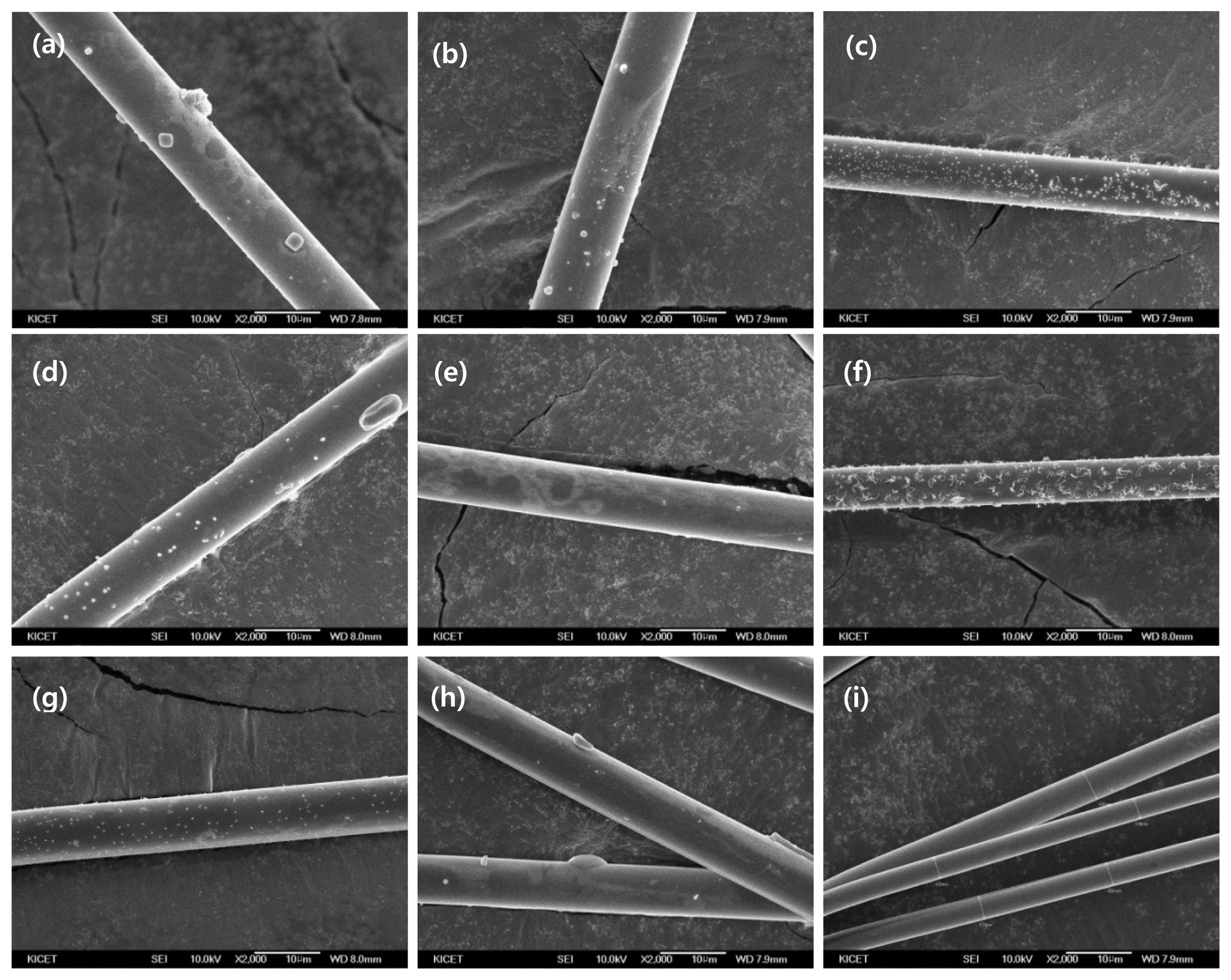
Change of diameter in 75°C NaOH solution from 3 mol to 9 mol by 1 to 5 h using FE-SEM (2kx). (a) 3 mol for 1 h (b) 3 mol for 2 h (c) 3 mol for 5 h (d) 6 mol for 1 h (e) 6 mol for 2 h (f) 6 mol for 5 h (g) 9 mol for 1 h (h) 9 mol for 2 h (i) 9 mol for 5 h.
It was found that the diameter was affected by the reaction time in the alkaline aqueous solution, but the change was not significant. This was because the concentration of the solution was too low to noticeably dissolve the E-glass fibers. The same procedure was repeated using an alkaline aqueous solution with a concentration of 6 mol. The fiber diameter was measured while varying the reaction time from zero to five hours. As a result, it was found that the diameter decreased with increasing reaction time, and the degree of change was larger than in the 3-mol solution. It was found that the diameter reduction of the E-glass fibers was the fastest when the concentration was increased to 9 mol, at the same temperature as in the previous cases. After five hours of reaction, the fiber diameter was measured to be 3.66 μm, which was a 63.69% reduction from that before the treatment.
The diameter measurements obtained from Fig. 2 were plotted, as shown in Fig. 3. As can be seen in the graphs, at 75°C, the diameter reduction rate of the E-glass fibers tends to increase with increasing alkaline concentration (mol). Also, it is noted that the 9-mol solution graph does not reach saturation but continues to decrease with increasing reaction time. This implies that at 75°C, the application of an even higher alkaline concentration or longer reaction time will further promote the dissolution of E-Glass fibers because the reaction between the alkalis and the fibers is expected to continue over time.

The graph of glass fiber diameter reduction in different mol concentration and reaction time of NaOH solution at 75°C.
The reaction temperature was increased to 85°C, and the same procedure was repeated. The resultant FE-SEM images are presented in Fig. 4. The results showed that the fiber diameter was noticeably reduced compared to when the reaction temperature was 75°C. After five hours of reaction in a 9-mol solution, the fibers were significantly smaller in diameter than those obtained at 75°C, as observed in the FE-SEM images. Also, even after one hour of reaction time, the fiber diameter was found to be smaller when reacted at 85°C than at 75°C. It was also found that regardless of the reaction temperature or time, the fiber diameter tended to decrease with increasing alkaline concentration (mol), as similarly observed in the 75°C case. Fig. 5 shows that the 9-mol graph increased as the reaction time was increased from two hours to three hours. This slight deviation is considered to be an error arising from non-uniform mixing in the beakers.

Change of diameter in 85°C NaOH solution from 3 mol to 9 mol by 1 to 5 h using FE-SEM (2kx). (a) 3 mol for 1 h (b) 3 mol for 2 h (c) 3 mol for 5 h (d) 6 mol for 1 h (e) 6 mol for 2 h (f) 6 mol for 5 h (g) 9 mol for 1 h (h) 9 mol for 2 h (i) 9 mol for 5 h.
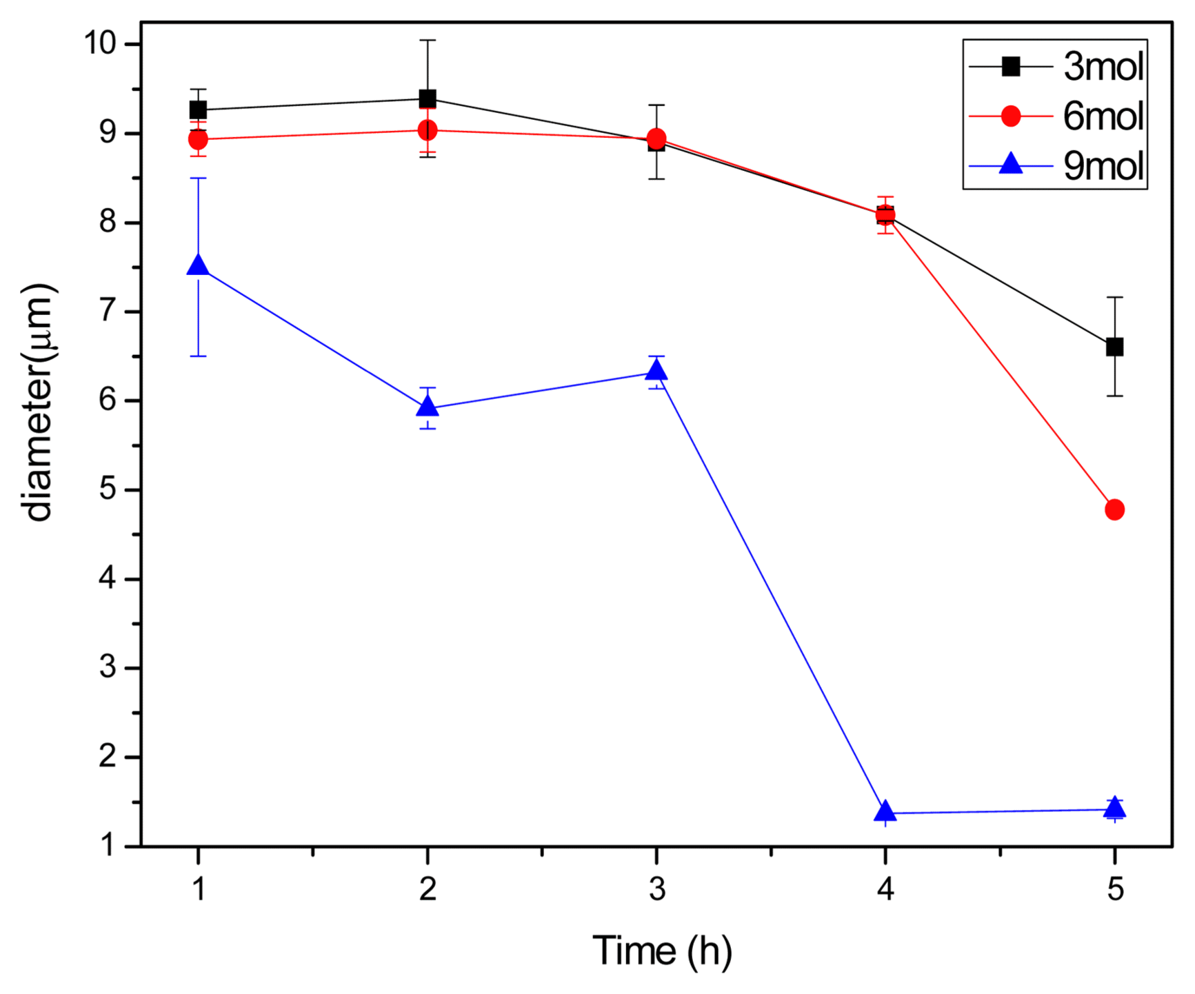
The graph of glass fiber diameter reduction in different mol concentration of NaOH solution at 85°C.
When the reaction temperature was 95°C, the diameter reduction in the 9-mol alkaline aqueous solution was faster than at the other temperatures, as shown in Fig. 6. Even after three hours of reaction, the fiber diameter was noticeably reduced to an extent that could not be achieved at the other reaction temperatures. After five hours of reaction time, the fiber surface was no longer smooth but became rough. This was because the fibers were too thin to allow for uniform diameter reduction. Here, the fiber diameter was measured to be 1.99 μm, which was an 80.26% reduction from that before the treatment. At 95°C, the diameter reduction rate was found to continue to increase with increasing reaction time which is shown in Fig. 7, unlike at the other reaction temperatures. This implies that the E-glass fibers and alkalis were sufficiently reacted during the dissolution process.8)
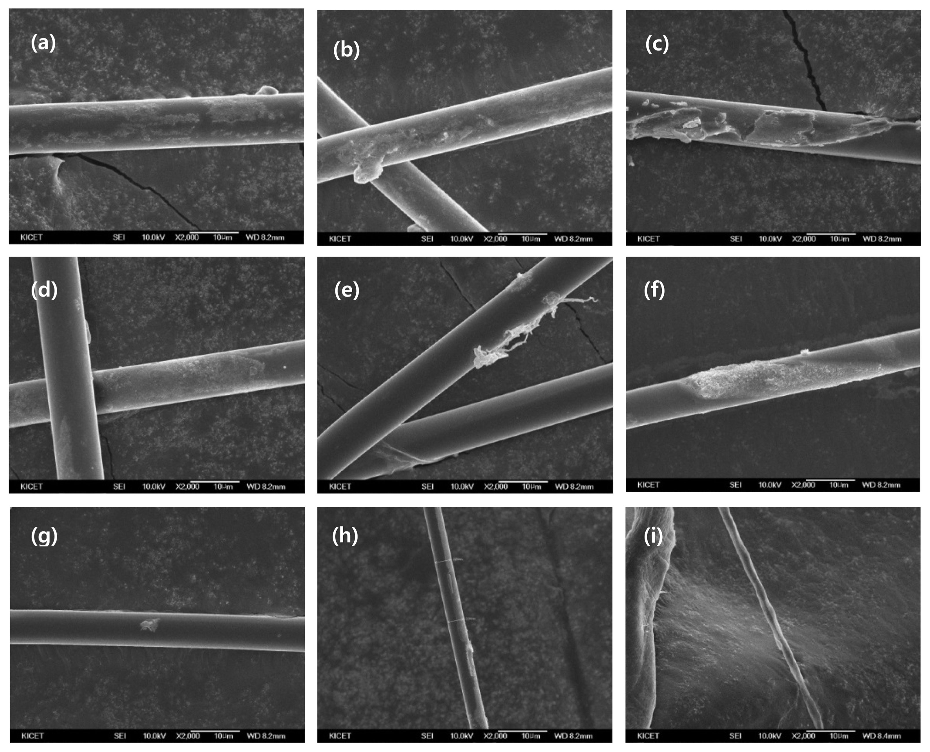
Change of diameter in 95°C NaOH solution from 3 mol to 9 mol by 1 to 5 h using FE-SEM (2kx). (a) 3 mol for 1 h (b) 3 mol for 2 h (c) 3 mol for 5 h (d) 6 mol for 1 h (e) 6 mol for 2 h (f) 6 mol for 5 h (g) 9 mol for 1 h (h) 9 mol for 2 h (i) 9 mol for 5 h.
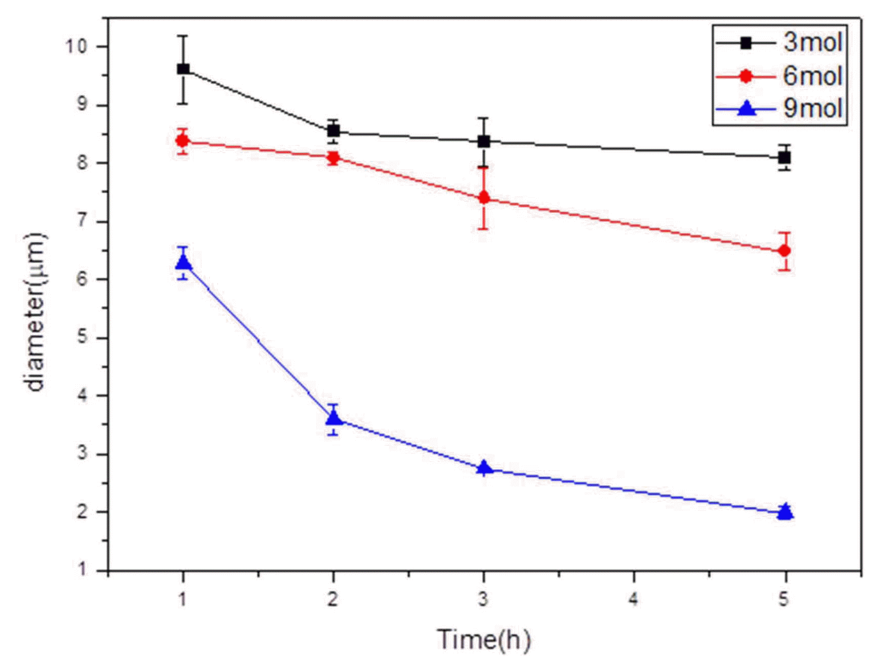
The graph of glass fiber diameter reduction in different mol concentration of NaOH solution at 95°C.
At all reaction temperatures, the dissolution rate of the E-glass fibers was found to be higher when the alkaline concentration was higher, given that the reaction time was the same, as shown in Fig. 8. Also, when the alkaline concentration was higher, the onset of dissolution at the fiber surface occurred earlier, and this was because the reactivity of alkali ions per unit area of the E-Glass fiber was larger. This relationship can be expressed as Eq. (1) below.8,13)
4. Conclusions
The present study examined the recycling of E-glass fibers, as a preliminary study for developing recycling technology for waste GFRP, in an attempt to address relevant problems, including difficulties in its waste treatment and cost concerns. E-glass fibers were dissolved in alkaline aqueous solutions with varying concentrations under various reaction conditions, and the reduction of their diameter was observed. It was found that the diameter reduction was more pronounced when the alkaline concentration and reaction temperature were higher. The most effective dissolution was achieved at 95°C. When the reaction time was the same, the diameter reduction was noticeably larger than at the other reaction temperatures. It was also found that the diameter reduction rate continued to increase as the alkaline concentration increased, reaching 9mol, and the reaction time reached five hours.
As such, the present study observed how E-glass fibers were dissolved in alkaline aqueous solutions under various reaction conditions. Future studies may focus on the dissolution of glass fiber-reinforced composites. The major findings of the present study are expected to be used as basic research data for future studies on the recycling of E-glass fibers.

