Role of Different Oxide to Fuel Ratios in Solution Combustion Synthesis of SnO2 Nanoparticles
Article information
Abstract
Tin oxide (SnO2) nanoparticles have been synthesized by solution combustion method using citric acid as a fuel. The oxide to fuel ratio has been varied to obtain ultrafine nanoparticles with better surface area; such particles will be useful in many applications. With this synthesis method, spherical particles are formed having a particle size in the range of 11–30 nm and BET surface area of ~ 24 m2/g. The degree of agglomeration of SnO2 nanoparticles has been calculated.
1. Introduction
Semiconductor oxides are a very important class of materials because they possess excellent properties and have seen wide application in various areas of science and technology like solar energy conversion, photo catalysis, gas sensors, and optoelectronics.1,2) They have been extensively studied from both experimental and theoretical points of view.3 Compared with their bulk counterparts, nanostructured semiconductor oxides retain rich morphologies and unusual physical and chemical properties,4 due to which they have wide potential application in nanoscale devices.5 Tin oxide (SnO2) has been widely studied as an n-type semi-conductor; it has a band gap energy of 3.6 eV at room temperature and has been used as a promising material for gas sensors and optoelectronic devices, and as a negative electrode for lithium batteries.6)
To synthesize versatile nanoparticles of SnO2, a variety of synthesis methods have been developed, including thermal evaporation, hydrothermal growth, solvothermal growth, pulsed laser deposition, electrospinning, sol-gel, co-precipitation, and so on. To implement these methods, however, many toxic chemicals are required; also, the cost of these synthesis techniques is high. In this regard, solution combustion synthesis is the best choice: it has emerged as a potential technique for the synthesis of metal oxide nano-materials and does not require any sophisticated instrument; also, it does not require as much time as is required for implementation of other techniques.7) However, there have been very few reports on SnO2 nanoparticles obtained by solution combustion synthesis.5–9) In the present work, we report the solution combustion synthesis of SnO2 nanoparticles using relatively low cost chemicals compared to those used in synthesis methods described in other reports.
2. Experimental Procedure
Typically, solution combustion synthesis requires metal nitrate precursors as oxidizers and an organic compound such as citric acid, urea, glycine, etc., as a fuel. Here, we use the chloride precursor of tin, i.e. SnCl2.2H2O. The other reactants used for the synthesis are ammonium nitrate (NH4NO3) and citric acid monohydrate (C6H8O7.H2O). The combustion was carried out with citric acid; it is generally called citrate-nitrate combustion synthesis or the citrate nitrate process (CNP).10) All the chemicals were used as received without further purification.
To form 1M of tin nitrate trihydrate (Sn(NO3)2.3H2O), 2M of ammonium nitrate must be added to 1M SnCl2.2H2O; the corresponding reaction is as follows,
The required amounts of SnCl2.2H2O and ammonium nitrate were dissolved in distilled water. As per the stoichiometric oxide to fuel (O/F) ratio, the solution of citric acid was prepared by dissolving the citric acid precursor in distilled water. This solution was added drop by drop into the solution of SnCl2.2H2O and ammonium nitrate while stirring at room temperature to form a homogeneous solution of metal nitrate and fuel. The solution was heated at 75°C on a hot plate for 1 h and the formation of a gel took place. Next, this gel was allowed to combust on a hot plate preheated to 375°C because the auto ignition temperature of citric acid is 345°C. The resultant ash was calcined in air at 600°C for 2 h to remove any carbon based residue that remained in the final product. The reaction that occurred can be written as follows:
For Stoichiometric O/F ratio of 0.44
Similarly, to optimize the O/F ratio and yield better properties of SnO2, SnO2 nanoparticles were synthesized with different fuel rich and fuel lean conditions, i.e. at different O/F ratios of 0.3, 0.44, 0.58, 0.72, and 0.86.
For the phase identification and crystallite size estimation, X-ray diffraction (XRD) studies were carried out. Thermogravimetric and Differential Thermal Analysis (TG-DTA) of the SnO2 nanoparticles was carried out to observe the weight loss with temperature. The morphology of the nanoparticles was studied using a field emission scanning electron microscope (FE-SEM). To confirm the presence of chlorine free particles, FTIR absorption spectra were obtained. Surface area analysis was carried out using the Brunauer–Emmet–Teller (BET) method.
3. Results and Discussion
3.1 TG-DTA Analysis
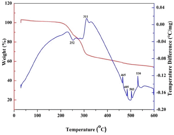
To study the thermal characteristics, TG-DTA analysis of the as-formed ash with O/F ratio of 0.4 was carried out from room temperature to 600°C with a heating rate of 5°C/min in air. Fig. 1 shows a TG-DTA plot for the O/F ratio of 0.4. The TGA plot shows two major weight losses of 32% and 12% in the temperature ranges of 197–311°C and 311–550°C, respectively, while there was very small weight loss of around 3% in the range of R.T. −100. The presences of one endothermic and 3–4 exothermic peaks in the DTA curve indicate the weight loss in the TGA. The weight loss from room temperature to 100°C can be attributed to desorption of moisture from the sample. The 32% weight loss is accompanied by an endothermic peak in the DTA curve at 252°C; this weight loss can be assigned to the decomposition of citrate groups and NO3− ions from the sample and the formation of SnO2. Further reduction in weight above 311°C, with the accompanying exothermic peaks in DTA, might be due to decomposition of the residual organic substance in the sample. An absence of any weight loss in the TGA, as well as the exothermic and endothermic peaks in the DTA curve above 550°C, confirms the formation of SnO2 at relatively low temperature. Hence the calcination temperature for all the samples was found to be 600°C.11)
3.2 XRD Studies
Phase confirmation of the SnO2 nanoparticles was carried out by XRD. XRD patterns of all the nanoparticles with different O/F ratios are shown in Fig. 2(a). From the XRD patterns it can be seen that all the diffraction planes due to tetragonal rutile SnO2 structure are present. No diffraction peaks corresponding to Sn or to other impurities are observed in the patterns. Only the holder peaks are observed. The calculated lattice parameters are in good agreement with the standard diffraction pattern. All the half peak widths are broad, indicating that the obtained crystallites have nanometer size and that this size varies between 11 – 30 nm.
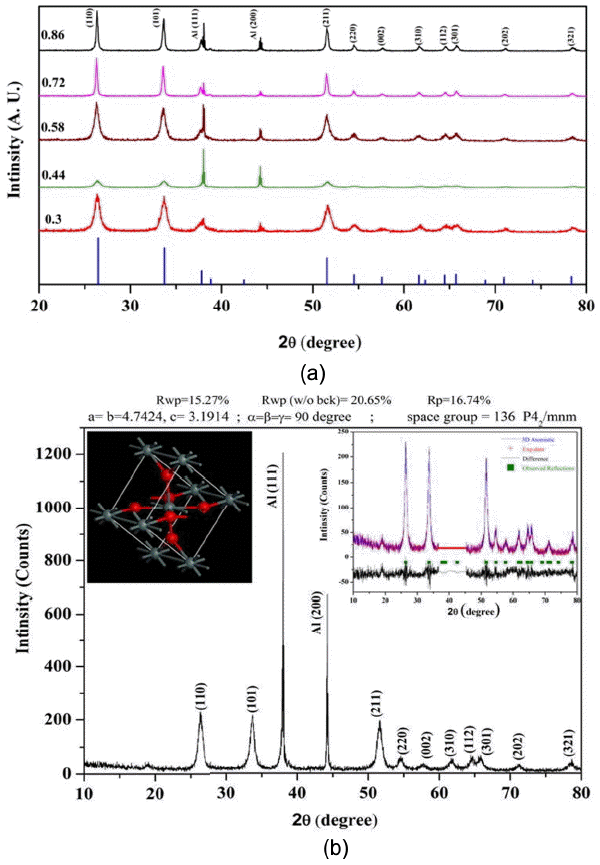
(a) XRD patterns of SnO2 with different O/F ratios compared with standard JCPDS (77-0452) pattern, and (b) XRD pattern of SnO2 with O/F ratio of 0.44. Inset shows Rietveld refined pattern for the same and corresponding unit cells.
Rietveld refinement of all the XRD patterns was carried out; results show that the refined lattice parameters are close to the reported values.3) The results for one of the samples with a stoichiometric O/F ratio of 0.44, obtained by Rietveld analysis, demonstrate the presence of a tetragonal rutile type structure, as shown in the inset of Fig. 2(b). This refinement of the SnO2 phase was performed on the tetragonal rutile structure with a space group P42/mnm (136). In this structure, a tin atom at the center is surrounded by six oxygen atoms at the vertex. On the basal plane side, the tin atom is bonded to four oxygen atoms with bonds of the same length; the tin atom is also bonded to the two apical oxygen atoms with two bonds of identical length (but this length is different from the bonds on the basal plane side). The unit cell of the Rietveld refined crystal structure is shown in the inset of Fig. 2(b). Rietveld refinement is probably the best-known method for determining accurate unit-cell parameters.
3.3 FTIR Studies
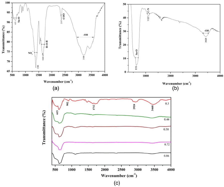
The FTIR spectra of the as-synthesized and the calcined SnO2 with O/F ratio of 0.44 are shown in Figs. 3(a) and (b), respectively. All the respective stretching vibrations are indicated in Fig. 3.12) It can be observed that after calcination of the nanoparticles the stretching vibrations due to CO2, NO3, and H2O become negligible, i.e. they almost vanish. Only weak absorption due to the water is present; the absorption band due to metal oxide, i.e. SnO2, becomes stronger after calcination, showing the phase formation of the SnO2 nanoparticles. FTIR spectra for all nanoparticles with different O/F ratios are shown in Fig. 3(c).
3.4 Morphology
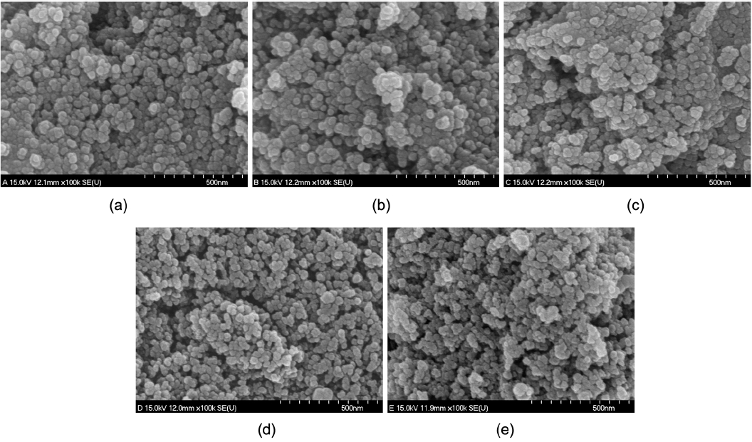
Figure 4 provides SEM micrographs of the calcined SnO2 nanoparticles. It can be observed that the ultrafine SnO2 particles are interconnected, which shows the strong agglomeration of the small spherical particles. This agglomeration consists of smaller grains with diameters in the range of 10–20 nm. These small particles result from the large volume of gases evolved during the strong combustion reaction. These gases, such as water vapor, N2, and CO2, act as igniters during the combustion process; this promotes the disintegration of the precursor, yielding nanocrystalline particles. These agglomerated nanoparticles form necks with their neighbors and hence form pores, ensuring high surface area.3)
3.5 BET Studies
The nitrogen adsorption and desorption isotherms for all samples were recorded at 77 K and are shown in Fig. 5 (a)–(b). The isotherms show hysteresis (according to the International Union of Pure and Applied Chemistry (IUPAC) classification), indicative of a porous structure. The size of the hysteresis loop is associated with the volume and connectivity of the pores. Hysteresis in the adsorption-desorption isotherm is indicative of a mesoporous structure. The isotherms for the nanoparticles synthesized with O/F ratios of 0.44, 0.33, and 0.58 are close to type IV, with an H4 hysteresis loop due to narrow slit pores.13)
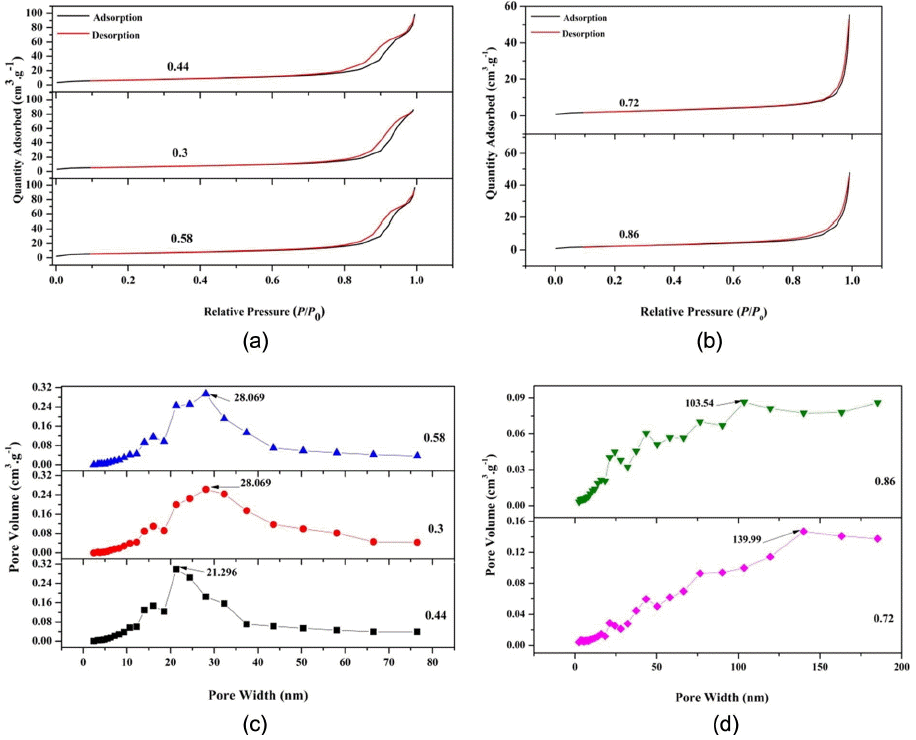
(a) Nitrogen adsorption and desorption isotherms for calcined SnO2 with O/F ratios of 0.44, 0.3 and 0.58, (b) Nitrogen adsorption and desorption isotherms for calcined SnO2 with O/F ratios of 0.72 and 0.86, (c) BJH pore size distribution for calcined SnO2 with O/F ratios of 0.44, 0.3, and 0.58, and (d) BJH pore size distribution for calcined SnO2 with O/F ratios of 0.72 and 0.86.
Figures 5(c) – (d) provide Barett-Joyner-Halenda (BJH) pore size distribution curves for all the samples. For the samples with O/F ratios of 0.3, 0.44, and 0.58 BJH, the curves show distinct maximum values at 28.069 nm, 21.296 nm, and 28.069 nm, respectively, indicating the mesoporous nature of the particles. On the other hand, for the O/F ratios of 0.72 and 0.86, the distinct maximum values can be seen at 139.99 nm and 103.54 nm, respectively, confirming the macroporous structure. This may be due to the higher fuel content, which causes in situ heating of the particles during the combustion process and hence results in large particles and pores.
The surface area of these samples was analyzed using the BET method. The surface area and total pore volume of each sample are tabulated in Table 1. The table shows that the surface area values of 0.72 and 0.86 were less than those of the other samples. This may be due to the formation of large pores with connected particles during the combustion process. The highest specific surface area, observed for the 0.44 sample, is 23.561 m2 g−1, while the lowest value, for the 0.72 sample, is 8.432 m2 g−1. The average particle size is calculated with BET using the following equation, Eq. (1),11,14)
where dBET is the average particle size, obtained from BET testing, ρ is the skeletal density in g/cm3= 6.95, and SBET is the specific surface area, obtained from BET testing. The degree of agglomeration is calculated using (dBET/dXRD).14)
4. Conclusions
In this paper we have reported a cost effective solution combustion synthesis of SnO2 nanoparticles in which we varied the O/F ratio. Very fine nanoparticles were obtained having crystallite size between 11–30 nm. Rietveld refinement of all the samples showed phase pure synthesis of SnO2 nanoparticles. SEM images show the formation of spherical nanoparticles with average diameter of 10–20 nm. BET surface area for the sample with an O/F ratio of 0.44 is ~ 24 m2/g; sample has a mesoporous structure. Hence, the optimized O/F ratio for the solution combustion synthesis of SnO2 is 0.44 because this value yields a better particle size and better surface area of the SnO2 nanoparticles; these qualities will be beneficial for further applications in gas sensors, photocatalysts, energy storage and conversion devices, etc.
Acknowledgments
This study was financially supported by Chonnam National University, 2014.
