


1. Introduction
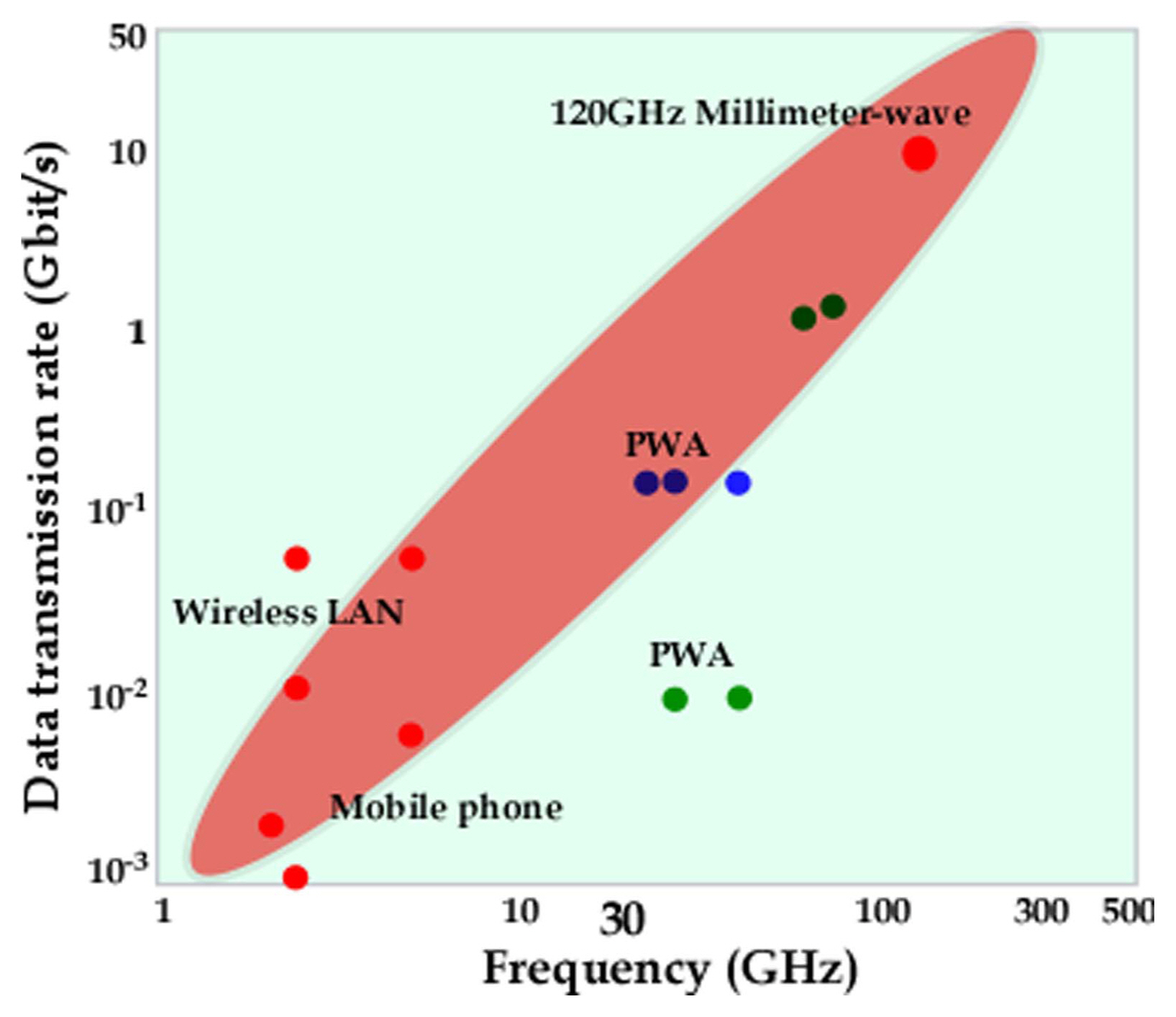
Technological advancements such as those represented in 5th generation (5G) and 6th (6G) generation mobile communication systems are expected to pave the way for many widely anticipated services such as eHealth and autonomous vehicles. These services require quick and unlimited wireless connectivity based on hyper-connected and global data-driven networks for making life smoother and safer. In particular, for 5G mobile communication systems, high-speed data transfer, low latency (time delay), and multi-connection facilities are required.1,2) Fig. 1 shows the data transfer rate as a function of frequency to achieve high data transfer rates at high frequencies.3) Consequently, for 5G and 6G networks, millimeter waves are expected to be applied for high-speed data transfer. The use of high frequencies generates dielectric losses as the inversion loss increases.4,5) So a high Q value can be expected.6-8) The time delay (latency) TPD becomes important for high-rate data transfer in 5G, as it is a function of the dielectric constant ɛr according to the following equation:9)
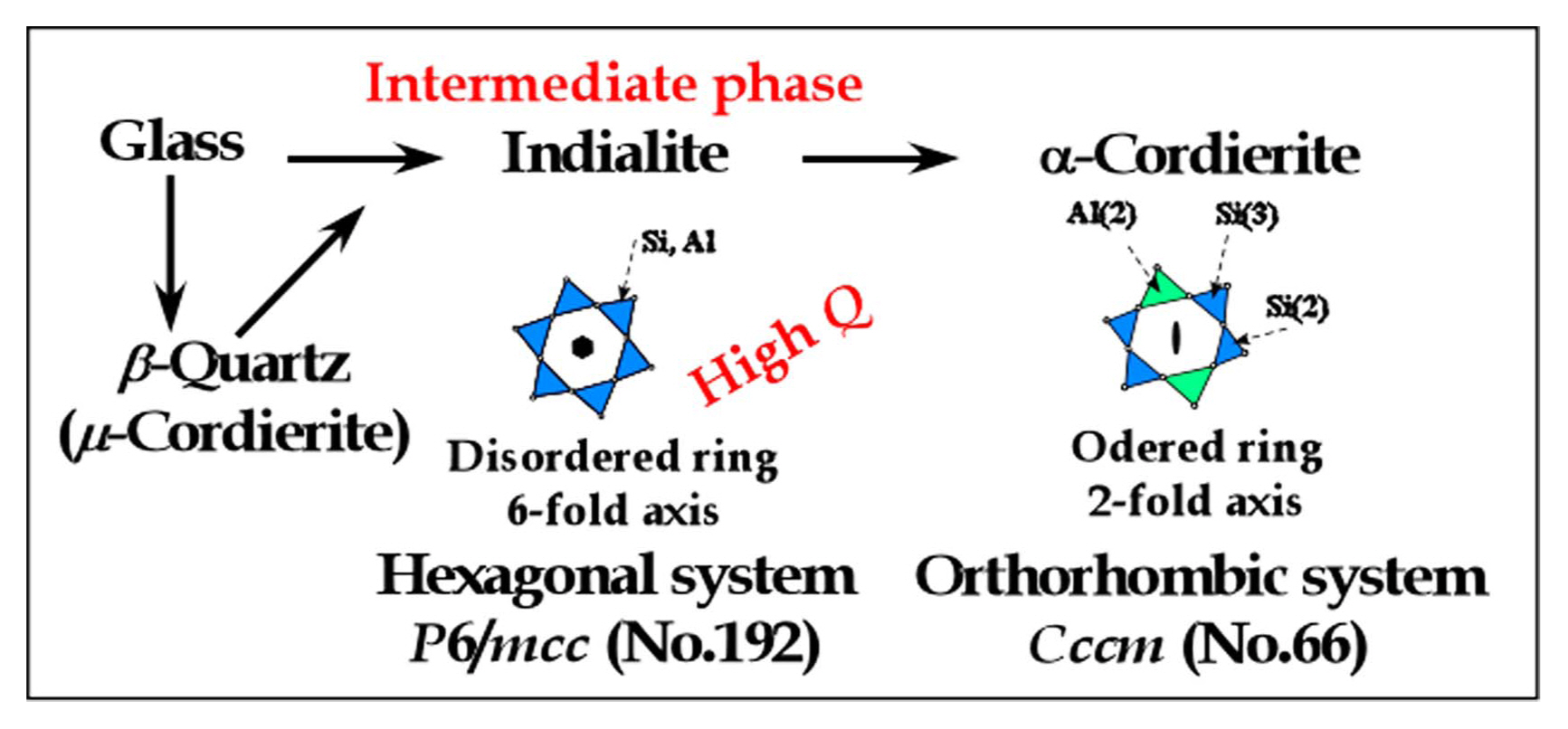
Here, c denotes the speed of light and ɛr the relative permittivity of the substrate or material. Hence, a critically low ɛr value is required for high signal speeds through the substrate/material. Silicates exhibit low ɛr values as the SiO4 tetrahedron affords a small rattling factor due to its Si-O bond mix of 55% covalent bonds and 45% ionic bonds.10-13) On the other hand, the TiO6 octahedron exhibits the highest ɛr value because of its significant rattling factor arising from the presence of Ti-O ionic bonds. Furthermore, corundum (Al2O3) exhibits a mid-range ɛr value because of repulsion between Ti-Ti bonds, which are shared in a 2:3 ratio in the octahedron. Terada et al. selected cordierite/silicates with low ɛr values for application to radio frequency communication networks because of their near-zero temperature coefficient of frequency (TCf) of - 24 ppm/°C.14-17) The authors found that the Qf of Ni-doped cordierite is improved from 40 × 103 to 100 × 103 GHz because of the resulting transformation from cordierite to indialite, as studied by Rietveld crystal structure analysis.15) Observations of the volume size and covalencies of AlO4 and SiO4 tetrahedra confirmed the transformation.17) Indialite precipitates from glass as a metastable phase; the possible formation of indialite based on the crystallization of the glass with cordierite composition is shown in Fig. 2.18-19) In this study, the microwave dielectric properties of indialite are shown to exhibit a low dielectric constant and high Qf when used as a resonator. Low-temperature co-fired ceramics (LTCCs)20) are fabricated using indialite powder with high Qf, and glass-ceramics substrates with low dielectric loss are fabricated via direct casting with the addition of TiO2 for volume crystallization to prevent the formation of cracks.
2. Experimental
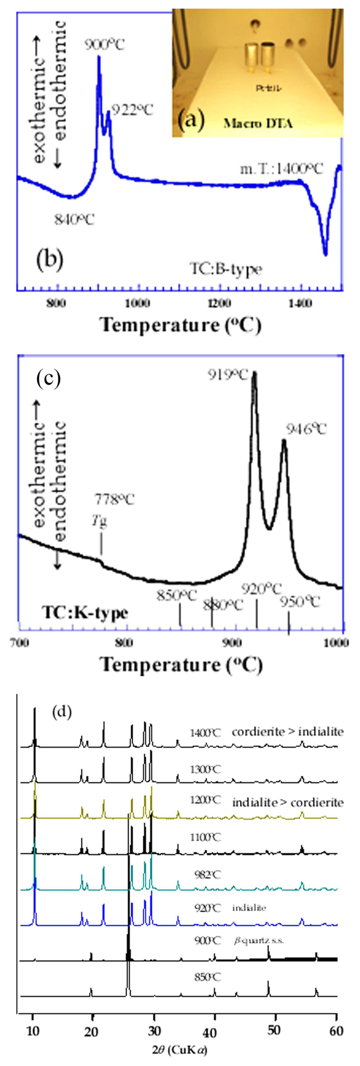
Glass with the cordierite composition of Mg2Al4Si5O18 was melted at 1550°C with clarification at 1600°C/1 h and then either cast in a graphite mold for the resonator, or directly cast as glass-ceramic substrates, or quenched in distilled water for the ceramic filler required for the LTCC tape casting slurry.18,19) The raw materials of MgO, Al2O3, and SiO2 had a high purity of >99.9%, and high-purity TiO2 was added for suitably adjusting the TCf value and as a nuclear additive for preventing cracking.21) The resultant glass exhibits high stress, and therefore, annealing under the glass transition temperature Tg is required for reducing the stress. The Tg value was obtained using differential thermal analysis (DTA), as shown in Fig. 3.22) The sample glass was cut for resonator fabrication and crushed for LTCC powder. Subsequently, the glass was crystallized at a suitable temperature for the resonator, direct casting substrates, and LTCC powder. The detailed procedures are explained in each relevant section.
The crystal structure of the specimens was measured via X-ray powder diffraction (XRPD; Bruker D8) using monochromatized Cu Kα radiation. The amount of indialite/cordierite was calculated by means of the Rietveld method using Fullprof Software.23) The bulk densities of the sintered samples were measured by the Archimedes method. The microstructural analysis of the green tapes and thermally etched sintered samples was performed by scanning electron microscopy (FESEM; Zeiss Ultra Plus).
The temperature coefficient of the relative permittivity (TCe) was measured using a precision LCR meter (Hewlett-Packard/Agilent Technologies 4284A) with a temperature chamber (Espec SU-261) operating in the temperature range of - 40 to 100°C. The microwave dielectric properties ɛr and Qf were determined by means of the Hakki-Coleman method,24,25) and TCf was estimated using the resonant cavity method. The coefficient of thermal expansion (CTE) was investigated in the temperature range of 100 to 600°C for cylindrical samples with dimensions of 8 mm × 15 mm using a dilatometer (NETZSCH DIL 402 PC/4).
The dielectric properties of the glass-ceramic substrates with 1 mm thickness were measured using the split-post dielectric resonator (SPDR) technique.26) The SPDR test is a quick test with minimal operator influence. It uses a resonator tuned to a specific frequency. The empty resonator is measured first. Subsequently, the sample is introduced into the resonator, and at the resonant frequency, any observed change is recorded. The dielectric constant ɛr is determined from the center of the frequency change together with an accurate measurement of the thickness of the sample. In our study, these properties were measured using a vector network analyzer (10 MHz-20 GHz, Rohde & Schwarz, ZVB20, Germany).
3. Results and Discussion
3.1. Indialite/cordierite glass-ceramic as high-Q resonator
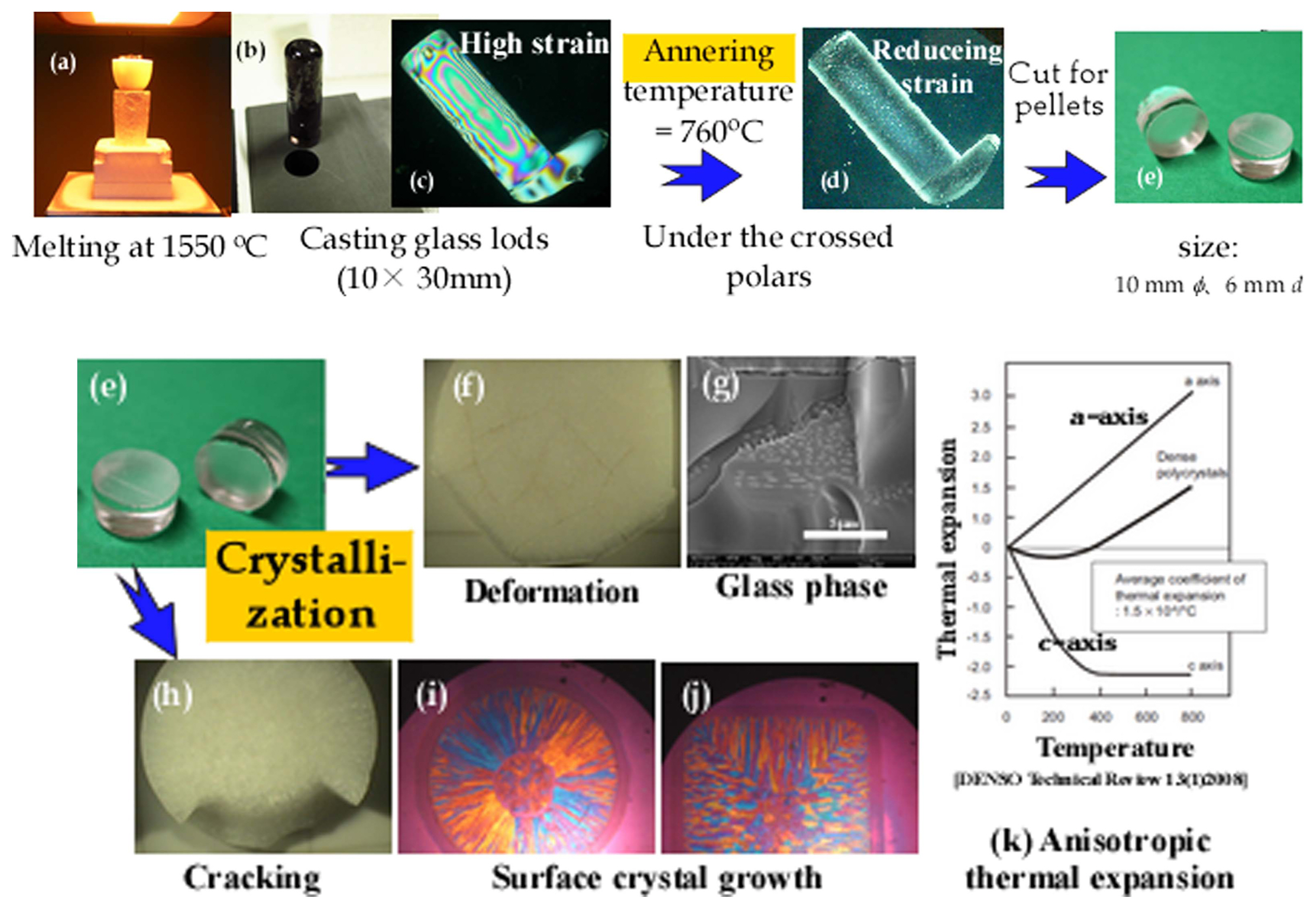
Figure 4 shows the fabrication procedure of a glass pellet with a radius of 10 mm and height of 5 mm. Glass melted at 1550°C was cast in a graphite mold with dimensions of 10 × 30 mm (in the form of rods). As the cast glass rods showed high strain, they were annealed and cut. The resulting pellets crystallized in the range of 1200 to 1450°C for 10/20 h exhibited cracking due to surface crystallization and deformation depending on the glass phase. These problems were overcome by adding TiO2 as a nucleating agent; this procedure is explained in a later section.
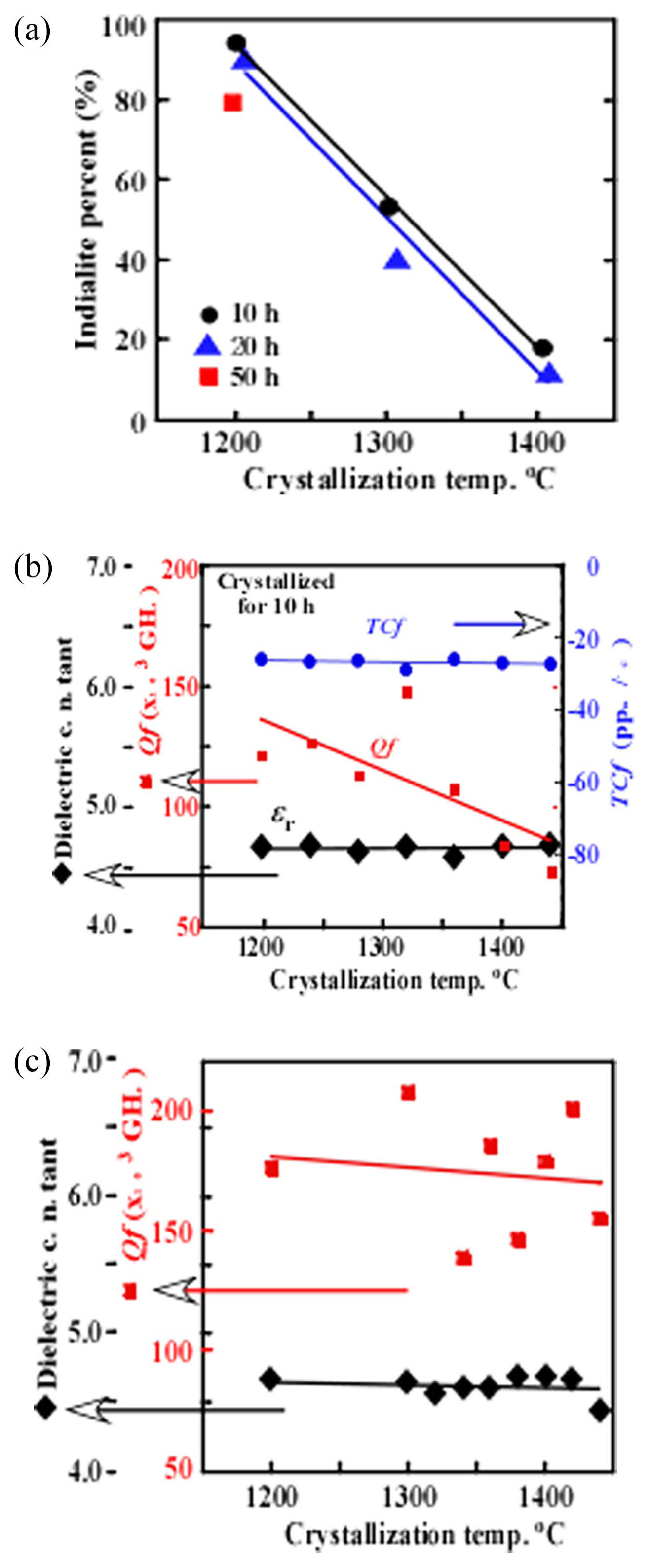
Figure 5(a) shows the amount of indialite (%) of the glassceramics and the microwave dielectric properties of the fabricated resonator as a function of the crystallized temperature. At a low temperature of 1200°C, the indialite percentage is >90%, and it is reduced to a low value of 20%, as shown in Fig. 5(a). Furthermore, the Qf values are reduced according to the crystallization temperature. Hence, it is clear that indialite has a higher Qf than cordierite. The highest obtained value is more than 200 × 103 GHz at 1300°C/20 h. Furthermore, the dielectric constant ɛr of 4.7 is the lowest value (as per previous silicate data), and the TCf value of - 27 ppm/°C is satisfactory with near-zero ppm/°C.
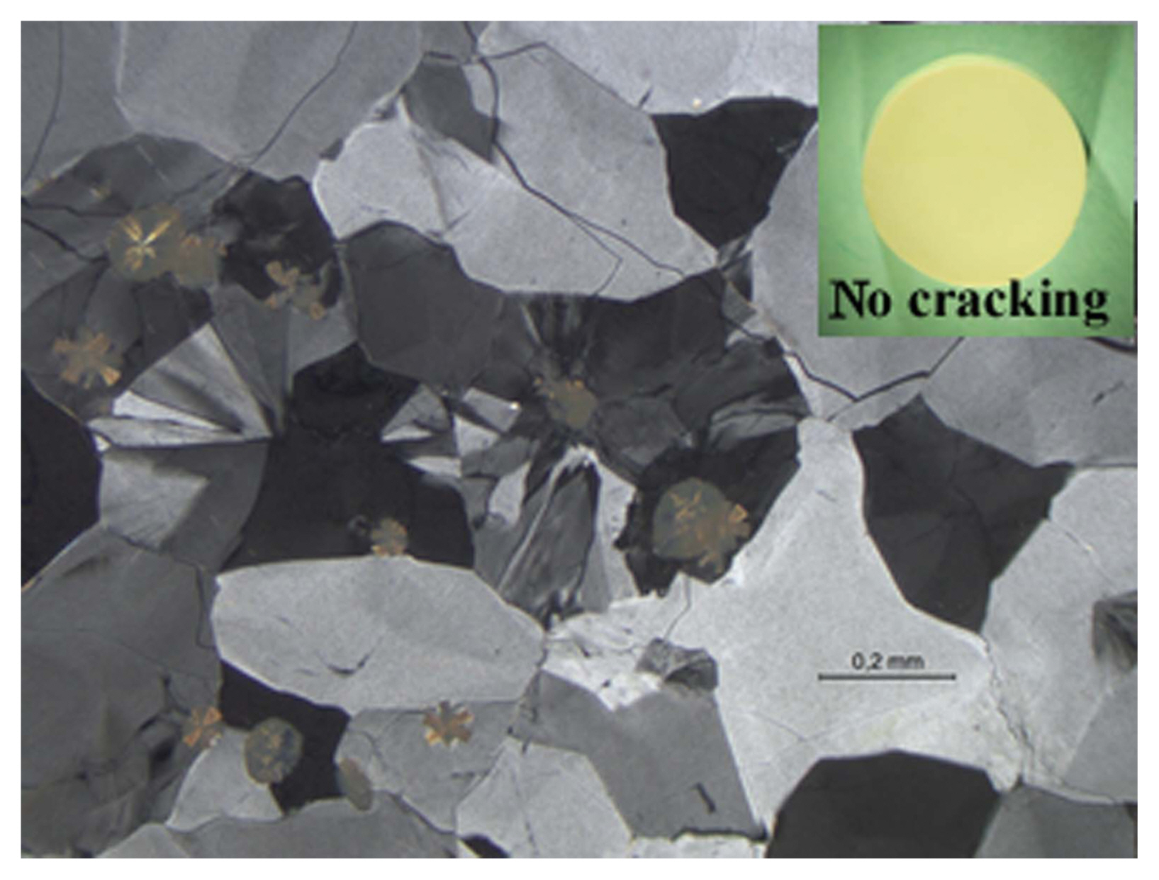
Sample cracking (Fig. 4(h)) depends on the surface crystallization, as shown in Figs. 4(i) and (j). When growing crystals from different surfaces meet, cracking occurs because of their different thermal expansions, as shown in Fig. 4(k).27) For preventing crack formation, 7 wt.% TiO2 as a nucleation agent was added, which reduced the cracking because of the occurrence of volume crystallization accompanied by surface crystallization, as shown in Fig. 6. The indialite/cordierite glass-ceramic with 10-wt.%-added TiO2 and crystallized at 1200°C/10 h has a low permittivity of 5.77/5.60, high Qf of 120 × 103/79.3 × 103 GHz, and TCf of - 13.5/- 20 ppm/°C, as per references28) and,29) respectively.
3.2. LTCC
LTCC substrate fabrication involved three steps: fabrication of indialite powder with high Qf, determination of low-temperature sintering conditions, and fabrication of LTCC substrates.20)
3.2.1. Fabrication of indialite powder for LTCC tape casting
Pure indialite was crystallized at 1000°C/1 h. The crystallization conditions were determined by DTA. Fig. 3(c) shows the DTA results, in which two peaks at 919 and 946°C are located. The first peak can be attributed to the crystallization of β-quartz and the second peak indicates the transformation from β-quartz to indialite. Fig. 3(d) shows the phases precipitated from the glass with the cordierite composition. β-quartz solid-solution is precipitated at 850°C, whereas indialite is precipitated at temperatures >920°C. The quenched glass with cordierite composition, crushed to a coarse grain size, was crystallized at the temperature of 1000°C/1 h to realize a pure indialite phase. Next, the crystallized glass was crushed to fine particles with sizes of 1-2 μm using planetary ball milling for the powder required for the LTCC tape casting slurry.20) The particle size and surface area analyses of the powder were performed using laser diffraction (Beckman Coulter LS 13320) and a particle surface area analyzer (G. W. Berg & Co. Micrometrics ASAP 2020).
3.2.2. Determination of low-temperature sintering conditions
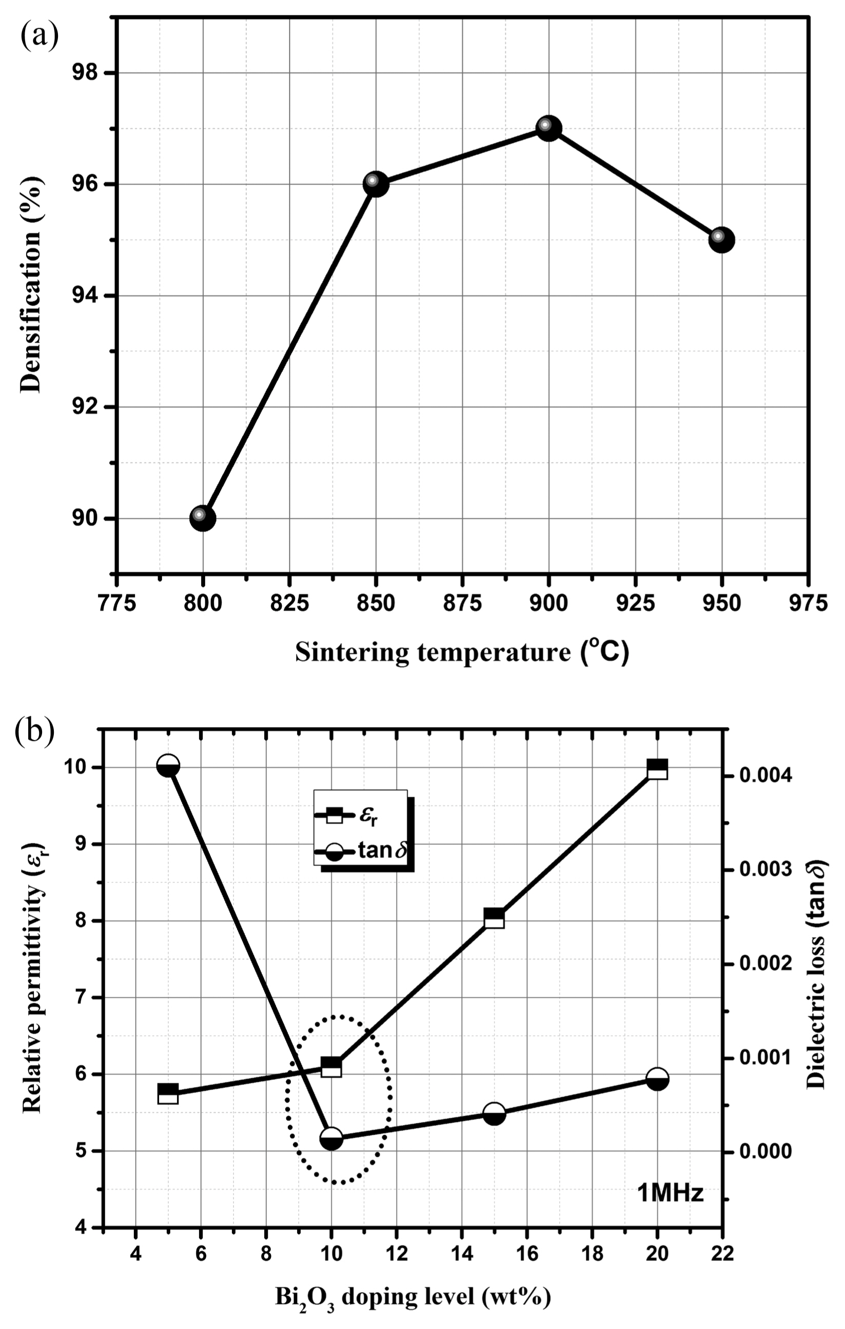
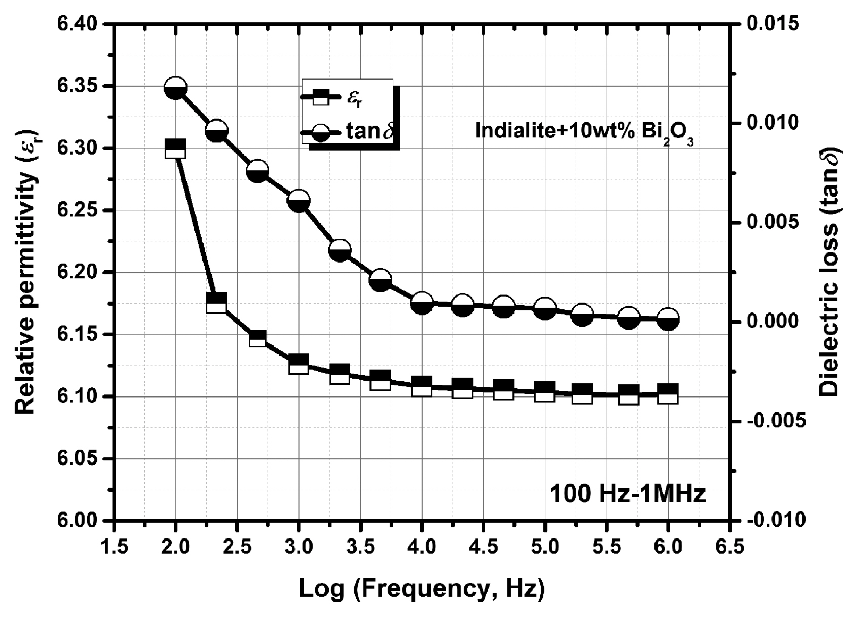
The low-temperature sintering conditions of indialite powder for LTCC fabrication were optimized using a Bi2O3 additive 20) and ZnO/B2O3 glass. In the case of Bi2O3, the sintering temperature of 900°C/2 h was determined by the densification of the 10-wt.%-Bi2O3-added sample, as shown in Fig. 7(a). The microwave dielectric properties of the relative permittivity and dielectric loss (tand) are 6.10 and 1.0 × 10⁻⁴, respectively, at 1 MHz for the 10-wt.%-Bi2O3-added samples sintered at 900°C/2 h, as shown in Fig. 7(b).
3.2.3. Fabrication of LTCC substrates
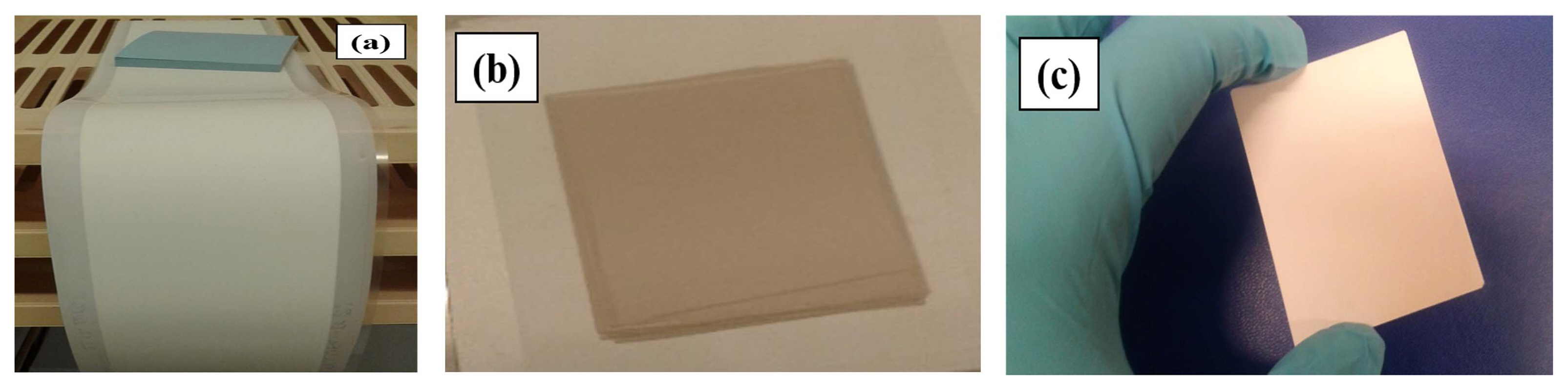
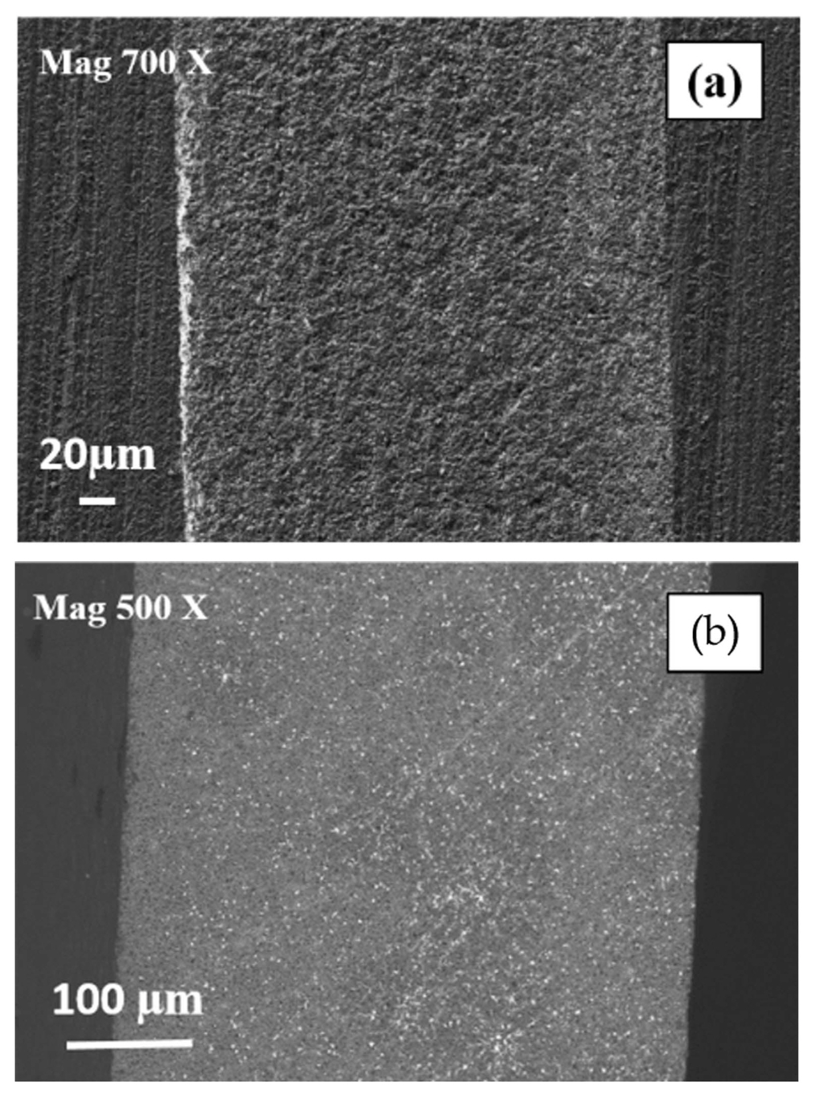
Low-temperature-sintered ceramic indialite substrates with five layers of green tapes for LTCC were fabricated.20) The initial average particle size of the sample ceramic mixture (10-wt.%-Bi2O3-added indialite) was 2.9 μm, and the single-point surface area at P/Po = 0.1998 was 15.52 m2/g. Based on these results, the slurry compositions were calculated as reported previously.30) The final tape casting slurry included xylene/ethanol, fish oil, PVA, BBP, and FEG added to indialite + 10 wt.% Bi2O3. Finally, the slurry was cast onto a silicon-coated Mylar carrier tape using a 400-μm doctor blade and sintered at 900°C/2 h after binder burnout. Fig. 8(a) shows the photographs of the green tape (a) with a thickness of ~120-130 mm, (b) thermally laminated tape with a five-layer stack, and (c) sintered substrate with a flat surface exhibiting no cracking. Figs. 9(a) and (b) depict the cross-sectional microstructure of the green single-layer tape and the sintered substrates with five layers, respectively. The dielectric properties of the 10-wt.%-Bi2O3-added indialite sintered at 900°C/2 h in the frequency range of 100 Hz to 1 MHz are shown in Fig. 10. The relative dielectric constant and dielectric loss at 100 Hz are 6.30 and 1.2 × 10⁻³ and decrease to 6.16 and 1.0 × 10⁻⁴ at 1 MHz, respectively. This relative dielectric constant is suitably low but higher than that expected for pure indialite because of the secondary Bi2SiO5 phase whose er data are unknown.30) The dielectric loss at 1 MHz is satisfactorily low compared with the reported one of commercial LTCCs,31) which is larger than that of the pure indialite phase because of the presence of the secondary phase. The temperature coefficient of the dielectric constant TCe was 118 ppm/°C, and dielectric loss varied from 1.0 × 10⁻⁶ to 2.0 × 10⁻³ in the measured temperature range of −40 to 100°C. The low-temperature-sintered substrate with er = 6.10 and tanδ = 1.4 × 10⁻⁴ at 1 MHz is an ideal candidate for LTCC applications. However, the micro/millimeter-wave dielectric properties were not very satisfactory (tanδ = 1.4 × 10⁻³) although the er value was low at 4.61 (Table 1). Hence, to improve the dielectric properties, we plan to use ZnO/B2O3 sintering additive with low loss in future; the casting and co-firing processes are currently underway. The CTE is 3.5 ppm/°C in the range from 100 to 600°C, which is less than those of other materials such as alumina (8.1 ppm/°C) and quartz (8-14 ppm/°C).
3.3. Direct casting glass-ceramic substrates
Indialite/cordierite glass-ceramic substrates fabricated by direct casting showed excellent dielectric properties, which will be schedule to make them applicable for patch antennas. In this section, fabrication method of the substrates, dielectric and are presented.
3.3.1. Fabrication
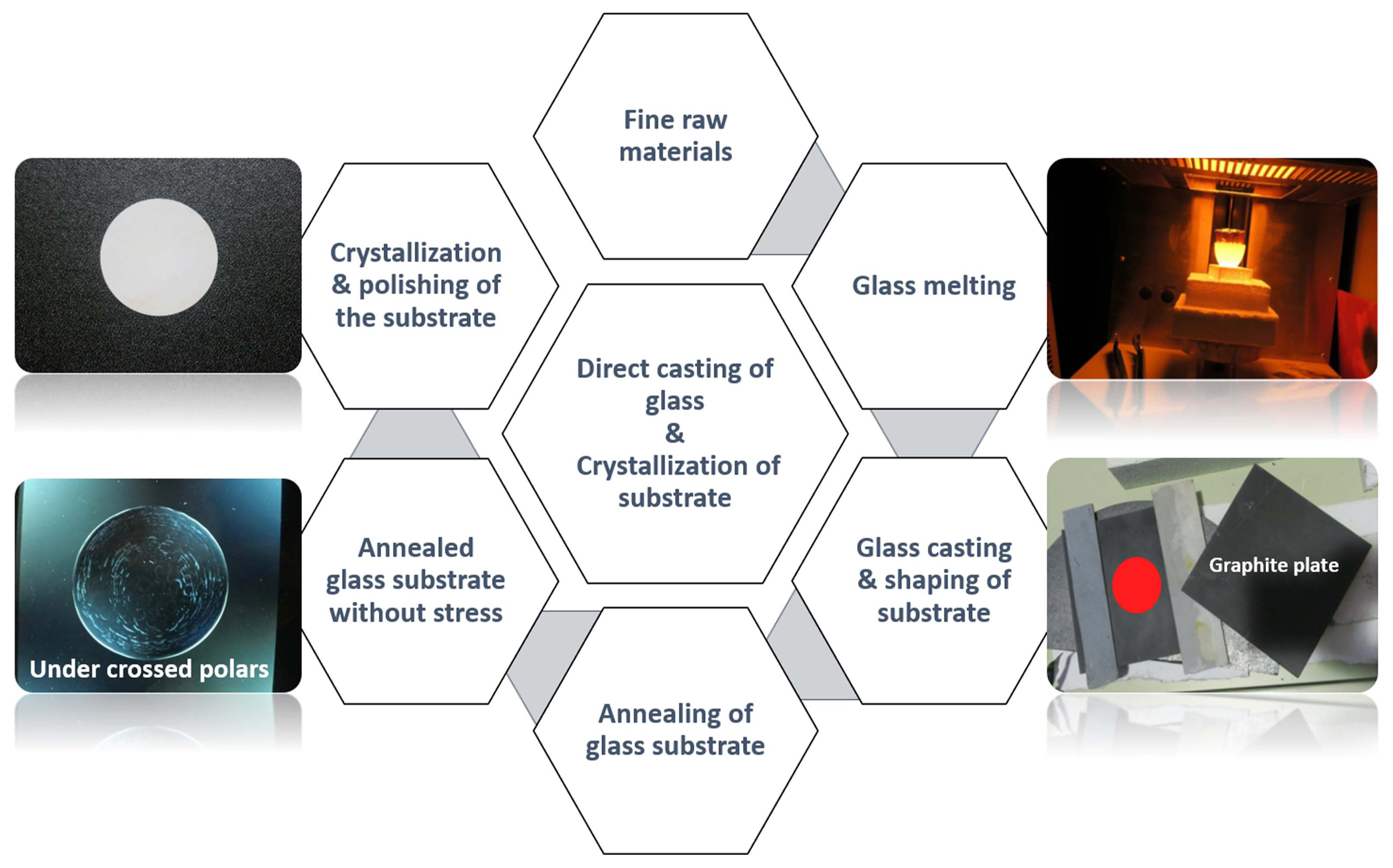
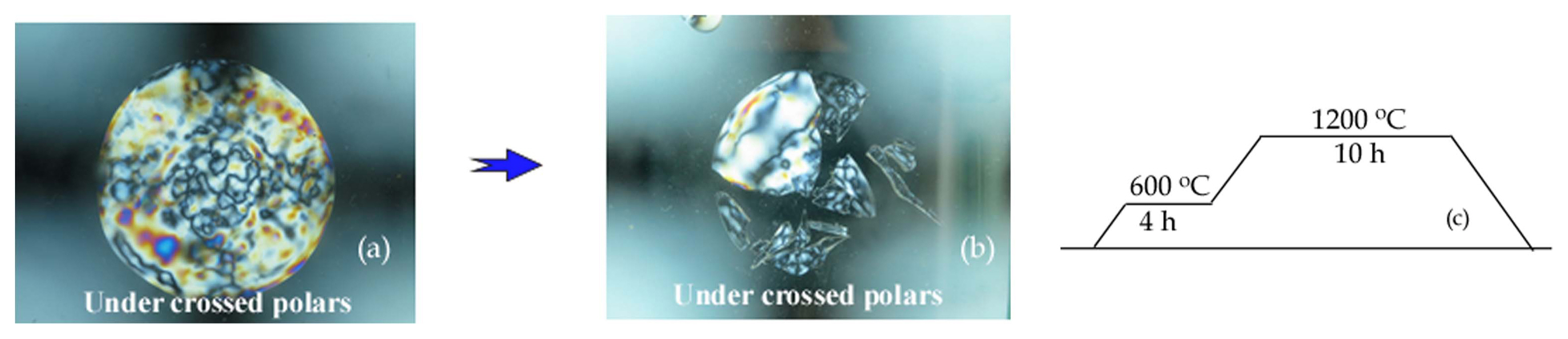
Figure 11 shows the procedure for the direct casting fabrication of glass-ceramic substrates: a mixture containing Mg2Al4Si5O18 composition and exquisite raw materials was melted and cast and shaped onto a graphite plane, to which 10 wt.% TiO2 was added to prevent crack formation.18,19) After annealing, the cast plates were crystallized at 1200°C/10 h and polished to a substrate with 1 mm thickness. Although the substrates did not undergo cracking upon volume crystallization during the crystallization process, during casting, the substrate exhibited breakage (Figs. 12(a) and (b)) after a few minutes/hours after casting. Therefore, the as-cast substrate was placed immediately in a furnace at 600°C and annealed for 4 h. The simplified annealing and crystallization processes are shown in Fig. 12(c). We note that these processes decrease the cost of ceramic fabrication.
3.3.2. Dielectric properties
The dielectric properties of the ceramics, measured by SRPD, are excellent (Table 2).26) The dielectric constant exhibits a low value of 5.58, which is increased due to the addition of TiO2; this ɛr value is higher than that of indialite (4.7). The dielectric loss (tand) of 2.27 × 10⁻⁴ at 5.1 GHz is highly satisfactory.
4. Concluding Remarks
The author reviewed the research at Hoseo University in Korea and University of Oulu in Finland. Research of indialite/cordierite glass-ceramics was begun at Hoseo University in 2009/8.19) The material science study of the glassceramics was mostly completed by 2016, after which he resigned as a Project Professor in NIT. Subsequently, Profs. Ohsato and Jantunen, at the University of Oulu, covered a wide range of research from material science to electronic devices. The fabrication of devices such as LTCC and direct casting glass-ceramic substrates was the outcome of the research.20 The glass-ceramics were fabricated in the NIT Ceramics Lab, Marusu Graze Company, and shipped to the University of Oulu. Currently, LTCC substrates and direct casting substrates composed of indialite/cordierite glass-ceramics have been developed20 and further research on LTCC is also in progress.