


1. Introduction
Reactive air brazing (RAB) is a simple, inexpensive and promising technique for joining dissimilar materials, which can be performed in air using a furnace without the need for any special apparatus. Earlier studies reported the effectiveness of RAB for joining a variety of ceramics and metal alloys using Ag-CuO fillers.1-10) The Ag-CuO phase diagram has eutectic and monotectic points at 932 and 964°C, respectively.2) Hence, RAB is generally performed for several minutes at temperatures higher than the melting temperature of the Ag-CuO filler. However, joint strength and morphology will vary with changing brazing parameters, which mainly include brazing temperature and holding time.5,11-14) Different researchers have used different brazing protocols for joining various materials.6,15-20) For instance, LSCF/FeCrAlloy and BCFZ/FeCrAlloy joints were brazed at temperatures of 1020-1100°C for 30 to 180 minutes by Chen et al.6) BSCF/AISI 314 joints were successfully brazed for 20 minutes at a brazing temperature of 955°C.15) YSZ/AISI 314 and BSCF/Crofer 22 H joints were brazed at 970°C for 20 minutes using Ag3Cu filler.16) TSZ3Y/Crofer 22 H joints were brazed for only 5 minutes at a fixed temperature of 1000°C.17) Zirconia-toughened alumina was brazed with different Ni-based alloys at 1100°C for 30 minutes.18)
Ce0.9Gd0.1O2−δ-La0.7Sr0.3MnO3±δ (GDC-LSM) ceramics are recognized as one of the most promising oxygen transport membrane (OTM) materials.21,22) Crofer 22 APU, a ferritic stainless steel, is one of the most commercially available and inexpensive metal alloys, which has been developed for use at high temperatures. Due to the high Cr content (22-24 wt%), this alloy exhibits superior strength and oxidation resistance at high temperatures. Crofer 22 APU has been successfully brazed using Ag-CuO for solid oxide fuel cells and OTM applications.7,9,10,23) In our previous studies,7,9,10) we reported on the successful brazing of GDC-LSCF and GDC-LSM ceramics with Crofer 22 APU at a fixed temperature of 1050°C for 30 minutes.
In order to obtain superior joining properties in RAB, it is necessary to use optimal brazing temperatures and times. Exploring the optimal brazing parameters may provide guidance for practical applications. So far, no studies have suggested generalized optimal brazing parameters, since the brazing properties are strongly dependent on the brazed materials. Indeed, there are very few studies on the effects of varying brazing temperature and holding time on interfacial microstructures and mechanical properties. In this paper, we evaluate optimal brazing temperature and holding time by examining the interfacial microstructure and shear strength of GDC-LSM/Crofer 22 APU joints.
2. Experimental Procedure
Five different GDC-LSM/Crofer 22 APU joints were prepared by using different brazing parameters, as shown in Table 1. Details about the brazing parameters, fabrication of ceramics and the joining procedure are reported in our recent publication.9) The joints were brazed in air using a box furnace at different temperatures (1000, 1050, and 1100°C for 30 minutes) and for different times (10, 30, and 60 minutes at 1050°C) with a heating rate of 5°C/minute. Two types of joint structures were prepared: Interfacial microstructures were observed on a whole lap-joint and shear strength measurements were carried out using an offset lap-joint. Scanning electron microscopy (SEM: S-4800, Hitachi) was used to characterize the microstructure of joining interfaces and fractured surfaces. By using a universal testing machine (MTS Landmark, USA), the shear strength of the joints was evaluated at room temperature at a head speed of 0.05 mm/minute according to ASTM D905.24) An average of 3-5 joints are reported here for shear strength.
3. Results and Discussion
Cross-sectional SEM micrographs of GDC-LSM/Crofer 22 APU joints brazed at different brazing temperatures of 1000, 1050, and 1100°C for 30 minutes are compared in Fig. 1. The overview of joints brazed at 1000°C along with the ceramic/filler and filler/metal interfaces at higher magnifications are presented in Fig. 1(a), which shows that the joint is in complete fusion, without any defects. Moreover, both interfaces are free of cracks and sound joining was achieved. This may be attributed to two main factors: 1) adequate wetting behavior of the Ag-CuO filler, possessing low contact angles of 30.5° and 20.1° for ceramic and metal alloys, respectively;9) 2) reduced generation of thermal residual stress during cooling from brazing temperatures, owing to ceramic, filler and metal alloys having nearly comparable coefficient of thermal expansion values of ~ 12.7, 19 and 11.5 × 10⁻⁶ K−1, respectively.7,9)
The microstructure shown in Fig. 1(a) for 1000°C is similar to the microstructure observed in the case of GDC-LSCF/Crofer 22 APU and GDC-LSM/Crofer 22 APU joints brazed at 1050°C.7,9) For easy comparison, the microstructure of GDC-LSM/Crofer 22 APU joints published by our group elsewhere,9) is presented in Fig. 1(b). Four distinct regions can be clearly observed in the joints: GDC-LSM as ceramic (C), Ag-10 wt% of CuO braze filler (F), oxide layer (O), and Crofer 22 APU as metal alloy (M). Fig. 1(a) and (b) reveal that the thickness of the brazed zone between the ceramic and metal alloy was approximately 60-70 μm. There was no reaction zone detectable at the C/F interfaces, revealing only a few precipitated CuO particles, as shown in the magnified images. CuO did not react with the ceramic and it tended to nucleate at the interface during cooling. On the other hand, an oxide layer was formed between the F/M interfaces with a thickness of about 20-25 μm. The oxide layer was composed mainly of Fe, Cr and Cu, as evidenced from elemental analysis using EDS.9) The presence of Cu in the oxide layer suggests that the diffusion of Cu took place from the brazing zone to the oxide layer. According to the literature, Cr2O3 tends to form easily on the surface of the Crofer 22 APU due to the outward diffusion of Cr at the brazing temperatures.25,26) In addition, MnCr2O4, CuCr2O4 and FeCr2O4 spinel oxides are then formed by a reaction between Cr2O3 and Mn3O4, CuO and Fe2O3, respectively. Moreover, separation of oxide layers also takes place. The darker oxide phase (O1) corresponds to the spinel oxides formed, whereas the brighter oxide phase (O2) corresponds to the Fe2O3 phase.
Figure 1 shows that by increasing the brazing temperature from 1000 to 1050°C, two main changes can be observed: 1) grain growth of spinel oxides takes place and diffuses towards the filler and ceramic zones; 2) the microstructure of the oxide layer at the F/M interface becomes more rigid, while some pores can be seen in the oxide layer of joints brazed at 1000°C. However, by further increasing brazing temperature to 1100°C, a completely different morphology of the interfacial microstructure was observed, as shown in Fig. 1(c). The braze filler and oxide layer regions are completely mixed each other. More oxide layer is formed due to higher temperatures and it is difficult to distinguish filler and oxide regions.
To further explore this, studies were carried out on the joints brazed at 1050°C, with varying holding times, as the joints show relatively rigid microstructures at both interfaces (as evidenced from Fig. 1). Fig. 2 compares the cross-sectional SEM micrographs of GDC-LSM/Crofer 22 APU joints brazed for different times of 10 and 60 minutes at a fixed temperature of 1050°C. It can be seen from Fig. 2 that the overall microstructures, including ceramic/filler and filler/metal alloy interfaces, are almost identical. The main difference between them is that with increasing holding time, more of the oxide layer is diffused towards the filler and ceramic regions.
Shear strengths of all joints are also presented in Table 1. It can be seen that as the brazing temperature increases from 1000°C to 1050°C, shear strength decreases marginally from 91±8 to 89±9 MPa. Increasing temperature further to 1100 °C, shear strength decreases drastically to 18±5 MPa. On the other hand, if the holding time is increased from 10 to 60 minutes, shear strength decreases continuously from 100±6 to 53±8 MPa. Superior shear strength (100±6 MPa) can be observed at brazing conditions of 1050°C for 10 minutes. These results indicate that increasing brazing temperature and holding time decreases the shear strength values. This may be attributed to the increasing oxide layer (Figs. 1 and 2). However, higher brazing temperature has a more adverse effect on shear strength than a longer holding time. With increasing brazing temperature, additional formation of the oxide layer takes place at the filler/metal alloy interface and it diffuses more rapidly towards the ceramic filler. Moreover, the width of the oxide layer increases, while the width of residual brazing Ag-CuO filler gradually decreases. The interfacial microstructure of the brazed joints varied evidently with an increase in brazing temperature, which may have had a pivotal role in affecting the mechanical properties of the joints.
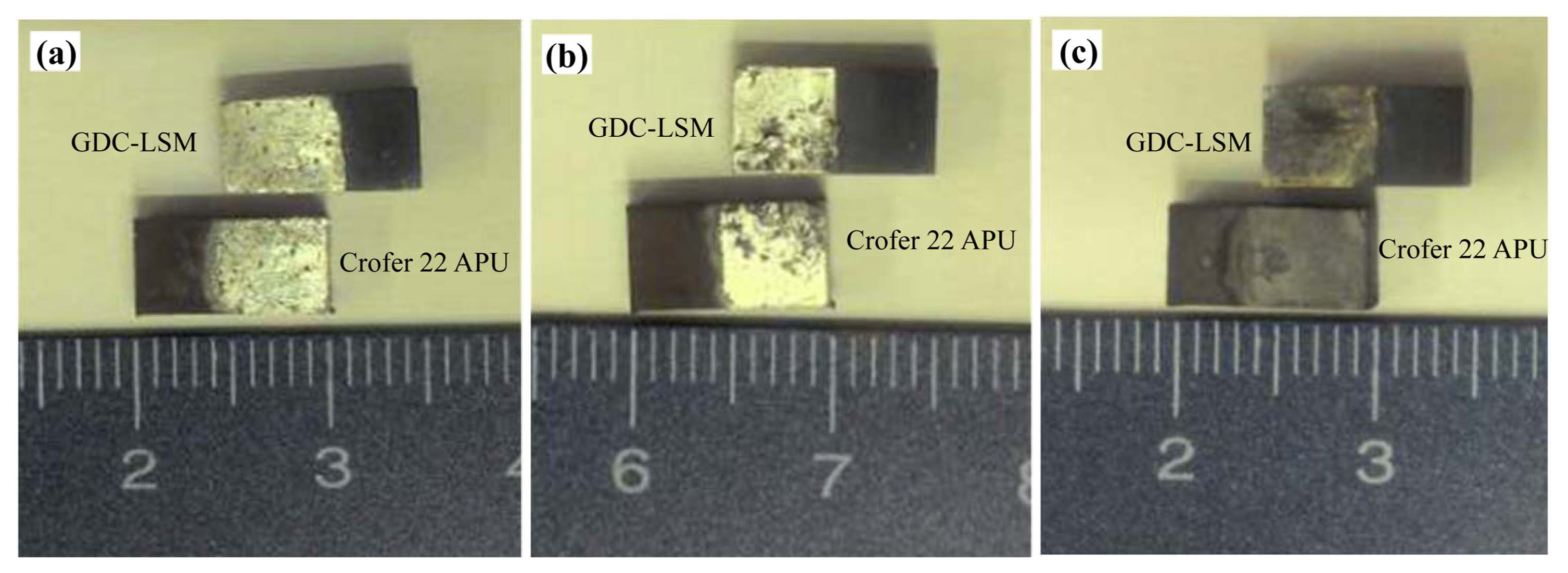
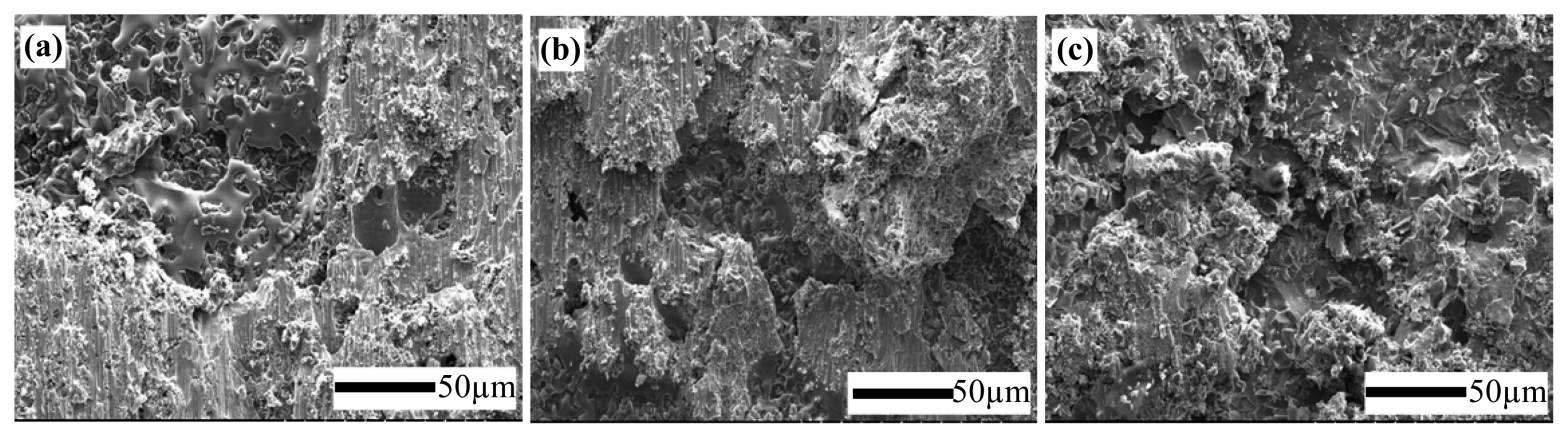
Figure 3 shows the digital camera images of fractured surfaces after shear strength tests of joints brazed at temperatures of 1000, 1050, and 1100°C, for 30 minutes. Fracturing occurred mainly at the joining interfaces and this indicates a cohesive failure. Fig. 4 shows typical fractographic SEM micrographs (ceramic surface) after cohesive fracture of joints brazed for 10, 30, and 60 minutes at a brazing temperature of 1050°C. A uniformly distributed and densely packed braze filler can be observed.
4. Summary
The effects of brazing temperatures and holding times on the interfacial microstructures and shear strengths were examined for GDC-LSM/Crofer 22 APU joints. Compact joining was achieved for all joints without the presence of cracks. The results showed that with increasing brazing temperatures and holding times, joint microstructure was clearly changed and shear strengths were decreased. Particularly, the use of brazing temperatures of 1100°C for 30 minutes is detrimental to shear strengths. Furthermore, the use of longer holding times at 1050°C is not necessary for brazing. Finally, this study suggests the use of optimal brazing condition of 1050°C for 10 minutes, as this offers the highest shear strength of 100±6 MPa.