Effect of Substrate Rotation on the Phase Evolution and Microstructure of 8YSZ Coatings Fabricated by EB-PVD
Article information
Abstract
The effect of substrate rotation speed on the phase forming behavior and microstructural variation of 8 wt% yttria (Y2O3) stabilized ZrO2 (8YSZ) coatings as a thermal barrier coating has been investigated. 8YSZ coatings with 100 ~ 200 μm thickness were deposited by electron beam-physical vapor deposition onto a super alloy (Ni-Cr-Co-Al) substrate with a bond coating (NiCo-CrAlY). The width of the columnar grains of the 8YSZ coatings increased with increasing substrate rotation speed from 1 to 30 rpm at a substrate temperature range of 900 ~ 950°C. In spite of the different growth behaviors of coatings with different substrate rotation speeds, the phases of each coating were not changed remarkably. Even after post heat treatments with various conditions of the coated specimens fabricated at 20 rpm, only a change of color was noticeable, without any remarkable change in the phase or microstructure.
1. Introduction
The thermal barrier coating (TBC) technology was developed as a protective ceramic coating technology, providing exceptional high temperature durability for electricity generating gas turbines and aircraft turbine engines. The main function of the TBC is to increase energy efficiency and allow stable operation of the system by protecting the metal alloy parts employed in the turbine system from the hot corrosive gas stream flowing through the compressor1–5). In general, a TBC, which is directly exposed to a gas environment at high temperature, consists of a ceramic top coating and a metal alloy bond coating and a Ni-based superalloy substrate. The material used as the top coating is commercially available zirconia (ZrO2), specifically, 6–8 wt% yttria (Y2O3) stabilized zirconia, which has been reported to afford the highest performance as a TBC material.6–9)
For the coating method for the top coating, an atmospheric/air plasma spray (APS) coating technology has been widely used on the strength of its low thermal conductivity and high economic efficiency.3,10,11) The APS deposition technology is implemented by using ceramic powder and plasma torch at high temperature, in excess of 3000°C, to produce powder melts and then attach them onto the metal substrate. However, these methods are known to result in low thermo-mechanical durability in applications involving long periods of operation due to structural imperfection such as un-melted particles, and pores between the lamellar type layers, and microcracks based on the splats stacking structure.3,10,11) Recently, to improve the structure of this kind of APS coating technology, various studies on new coating technologies have been carried out, including suspension/slurry precursor plasma spray, electron beam-physical vapor deposition (EB-PVD), plasma spray-physical vapor deposition and so on.3,10,11)
Among these coating methods, EB-PVD deposits ceramic materials on the substrate by melting and evaporating a sintered body produced from the ceramic powders, by irradiating them with an electron beam generated in a high vacuum of under 10−4 torr. In this case, the vapor phase particles can induce the growth of a columnar coating structure, which is known to enhance the final product’s high temperature thermo-mechanical durability due to its excellent structural strain tolerance in thermal cyclic fatigue condition.12–19)
In particular, the control of material evaporation at the early stage of nucleation at the substrate could influence the growth behavior of columnar grains by altering the change of substrate rotation condition and the coating temperature.12–14) Schulz et al. reported that different substrate rotation conditions can affect the growth behavior of the film during vapor phase deposition by differentiating the vapor-impact angle on the substrate surface, even at a similar range of substrate temperature.13–14)
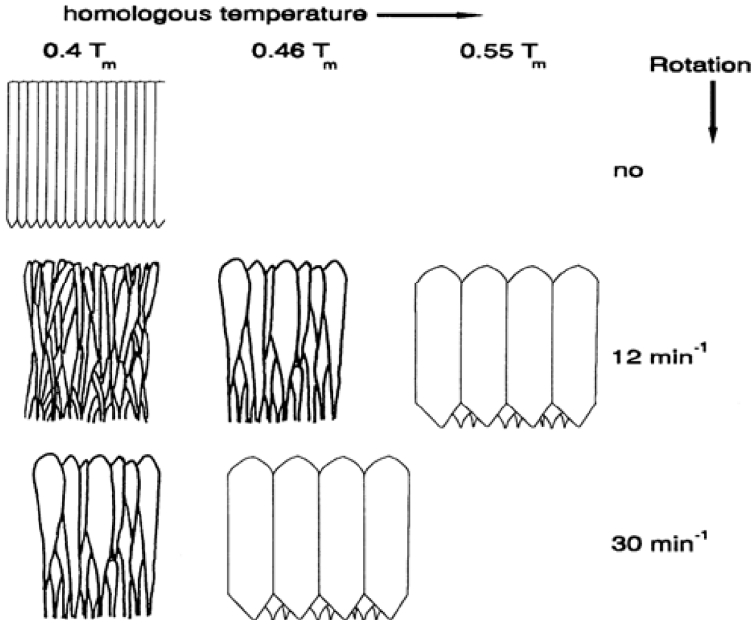
These factors can promote various shapes of columnar structure, which are related to ceramic fragmentation. The fragmentation of the columnar structure can influence the deformation resistance of the TBC, which is exposed to repetitive thermo-mechanical stress conditions. Fig. 1 presents a schematic illustration of changes in the columnar structure of the EB-PVD film according to the rotation speed and temperature of the substrate.12)
Previous research on the effects of deposition parameters on the grain growth of films in the case of vacuum deposition processes, such as electron beam evaporation processes, have predominantly focused on the depostition temperature, based on the structure-zone theory.13,14) However, other studies have addressed the complex effects of various process components of the film on the film growth behavior, including substrate chamber pressure, rotation of the substrate, surface roughness, and gas phase particle flux. In this paper, we have focused on the effect of the substrate rotation conditions on the film structure under uniform substrate temperature. 8 wt% yttria stabilized zirconia (8YSZ) coating samples were fabricated by EB-PVD with various rotation speeds of the substrate in a range of deposition temperatures in the range of 900 ~ 950°C, and the samples were investigated in terms of columnar growth and phase formation behavior.
2. Experimental Procedure
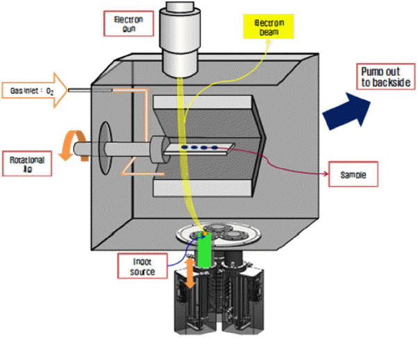
The substrates (Ni-Cr-Co-Al based super alloy (Mar-M 247) were prepared as disc shaped coupons, machined to a 1″ diameter and 3 mm thickness. 8 wt% Y2O3–ZrO2 (8YSZ, 99.7%, SEWON, KOREA) was used for the top coating. 8YSZ coating sources were prepared in the form of ingots. Initially, a green body of ingots was prepared by unidirectional pressing under 3 MPa and then heated at 1500°C for 3 h. A bond coating of 150 μm thickness was deposited in advance by the HVOF (High Velocity Oxygen Fuel) coating method using a conventional Ni-Co-Cr-Al-Y alloy powder (Amdry 386-2, Sulzer metco, Switzerland). Ceramic top coatings were fabricated by an EB-PVD system (VTS, Korea) installed in the laboratory. The EB-PVD system is illustrated schematically in Fig. 2.20) The EB-PVD system was equipped with an e-gun (max, 100 kW) with a customized rotatable substrate fixture. To deposit the ceramic top coating, the prepared substrate was installed on a fixture and placed under a vacuum. The substrate was heated to 950°C using graphite heating elements before coating and the same temperature was maintained until the end of the deposition process.
A coating process was performed at a rate of 1.5 μm/min under a vacuum of 2 × 10⁻⁴ torr using 20 kW electron beam power and 100 sccm O2 flow. In the experiment, the substrate rotation speed was varied as 1, 5, 10, 20, and 30 rpm during the deposition. Detailed sample information and coating conditions are provided in Table 1.
To verify the phase and microstructural changes of the top coatings after post-heat treatment, the coated specimens were heated at three different temperature and environment conditions. The first condition was vacuum heating at 1000°C/2 h. The second was conventional heating in air at 750°C/4 h. The third was a mixed condition of the first and second heating conditions. The above heat treatment conditions are known as the post heat treatment process when the bond coating is not processed by preoxidizing.12) In this case, vacuum heating improves the interface between the bond and the top coat, and the heat teatment in air supplements oxygen deficiency.
The surface and cross-sectional microstructure of the coated specimens were then analyzed by Field Emission Scanning Electron Microscopy (FESEM, JSM-6701F, Jeol, Japan). Additionally, an X-ray diffractometer (XRD, D-max-2500, Rigaku, Japan) with a Cu kα and 40 kV was used to analyze the phase forming behavior of the coating specimens.
3. Results and Discussion
The results of the phase formation behavior of samples coated at different substrate rotation speeds are shown in Fig. 3. Typical tetragonal phases of yttria stabilized zirconia with strong intensity of the (200) plane were identified in the specimens coated at low substrate rotation speeds of 1 and 5 rpm. On the other hand, the specimens coated at a medium rotation speed of 10 rpm showed more textured growth behavior on the (200) plane. The specimens coated at high substrate rotation speeds of 20 and 30 rpm showed more random growth tendency at the (111), (200), (220) and (311) planes.

Phase analysis of 8YSZ coatings prepared with different rotation speeds: (a) 1 rpm, (b) 5 rpm, (c) 10 rpm, (d) 20 rpm, and (e) 30 rpm condition.
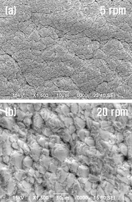
The surface morphologies of the specimens coated at relatively lower (5 rpm) and higher (20 rpm) rotation speeds are compared in Figs. 4(a) and 4(b), respectively. The specimen coated with a 5 rpm condition displayed a flocculated and/or beaded structure of small grains. In contrast, in the case of the coated specimen fabricated at a 20 rpm condition, a typical pyramidal shape of largely extended grains was observed.
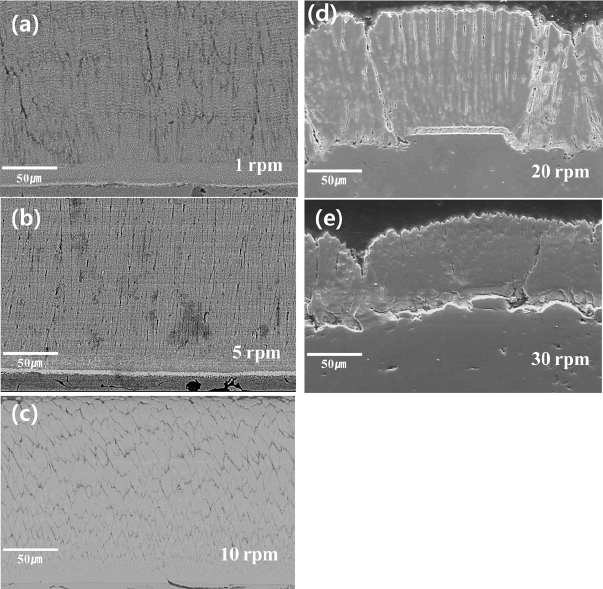
Cross-sectional views of 8YSZ specimens coated with different substrate rotation conditions are presented in Fig. 5. As seen in Fig. 4, different column structures are observed for coating specimens with different substrate rotation speeds. Namely, it appears that the nucleation and growth behavior of the grains are influenced by the rotation speed of the substrate. In the case of relatively low rotation speeds, 1 and 5 rpm, a denser and finer columnar structure is observed, as shown in Figs. 5(a) and 5(b), respectively, than other coatings with higher rotation speeds. The width of columns of these coatings was about 1 ~ 2 μm in the top area of coatings.

Cross-sectional view of 8YSZ top coatings prepared at different substrate rotation speeds of (a) 1 rpm, (b) 5 rpm, (c) 10 rpm, (d) 20 rpm, and (e) 30 rpm.
In the case of specimens coated with relatively higher rotation conditions, 20 and 30 rpm, the width of the columns is substantially extended compared to the coatings with lower rotation conditions, as shown in Fig. 5(d) and 5(e), respectively.
Schulze et al.13,21) reported that the columnar grains increased with an increase of substrate rotation speed, and the extension of the column width was clear at the top area of the coatings, as compared to the interface between the top and bond coatings. It was also found that inter-columnar pores were significantly expanded. Such inter-columnar pores are known to improve the strain tolerance of TBC by fragmenting the ceramic top layer.12)
Moreover, it was observed that the roughness of the substrate affected the growth behavior of the coatings, as seen in Figs. 5(d) and 5(e). In Fig. 5(d), in the case of a smooth surface area, the columns were grown regularly and showed uniform width. In contrast, in the case of a rough area, most of the columns were clustered with dense and inclined fine grains. In this case, it was expected that a reduction of structural strain tolerance might result from the unclear separation of each column.15)
As shown in Fig. 5(e), a clustered columnar structure was also observed with the rough surface area. If vaporized particles reached the rough surface, the vapor flux would not be uniform over the whole surface area, thereby resulting in differences in the surface diffusion of particles. Therefore the film growth behavior can be different at each site of the surface.12–14)
On the other hand, in the case of the coating with the 10 rpm condition as shown in Fig. 5(c), wider but shorter columns were found when compared to the coatings with lower rotation conditions. Such different growth behavior of grains might results from the specific conditions of chamber pressure and vapor flux as well as from shadow effect during the revolutionary deposition process.12–14,21)
Post heat treatment tests were performed to identify the phase and structural changes of the coatings, and also the change in the apparent color of the as-received coatings due to oxygen deficiency during the vacuum deposition process.12,13)
The phase change of the coating specimens that were fabricated with a 20 rpm substrate rotation condition was analyzed by XRD, and the results are presented in Fig. 6. The heat treatment conditions were set as mentioned in the experimental procedure. Generally, the phases of the coatings did not change significantly after all the types of heat treatment.12)

XRD analysis of 8YSZ coatings after heat treatment: (a) as-received, (b) after 1000°C in vacuum, (c) after 750°C in air, and (d) after 1000°C in vacuum and 750°C in air.
Figure 7 shows cross sectional views of the specimens coated at a 20 rpm rotation condition, before and after various post heat treatments. Compared to the as-received coated specimen, there are no particular changes in microstructures from the other heat treated coatings, except a certain tendency of grain refinements in the case of coatings after heat treatments in two kinds of air condition. Moreover, in the case of the coatings which received heat treatment in air after the heat treatment in vacuum, the intercolumnar gaps were more clearly observed after the heat treatment.

Cross-sectional views of 8YSZ coatings prepared with substrate rotation at 20 rpm after different heat treatment conditions: (a) as-received, (b) after 1000°C in vacuum, (c) after 750°C in air, and (d) after 1000°C in vacuum and 750°C in air.
The surface views of the specimens coated at the 20 rpm rotation condition are shown in Fig. 8, before and after various heat treatments. They also showed a similar trend of microstructural changes before and after heat treatment, as in the case of the cross section analysis results in Fig. 7. With respect to the surface color of the coatings, the dark gray color changed to a brighter color as shown in the insets of Figs. 8(a) and 8(d), respectively. As mentioned above, the dark color of the as-received coating specimen could be the result of a deficiency of oxygen when the deposition of oxide was performed in a vacuum condition. Such oxygen deficiency might affect the stoichiometry of the oxide in the local position of the structure, resulting in a change of color without remarkable phase and microstructural changes.12,13)
4. Conclusions
TBCs comprised of 8 wt% of yttria stabilized zirconia coatings with 100 ~ 200 μm thick fabricated by the EB-PVD method onto super alloy (Ni-Cr-Co-Al) substrates with a bond coat (Ni-Co-Cr-Al-Y). Even the substrate temperature condition was similar, a difference in the growth behavior of the coatings was found in the microstructural analysis, due to differences in the rotation speed during deposition; the column width of the each column was increased as rotation speed was increased. When the deposition processed on a rough substrate surface, it produced a clustering of grains with dense and fine grain. Also, it was found that the color of the as-fabricated coatings, dark gray, could be changed to a bright color by post heat treatment in an air condition without creating any remarkable change in the phase or microstructure of the top coating at temperatures under 1000°C, except for slight grain refinement.
Acknowledgments
This research was supported by a grant from the Fundamental R&D Program for Strategic Core Technology of Materials funded by the Ministry of Trade, Industry and Energy and by a grant from the Basic and Strategic R&D Program funded by the Korea Institute of Ceramic Engineering and Technology, Republic of Korea.


