


1. Introduction
Given current environmental demands, porous ceramic is a leading candidate for applications such as liquid gas filters, catalysis supports, gas distributors, insulators, preforms for metal-impregnated ceramic metal composites, and implantable bone scaffolds.1,2) While pores have been traditionally avoided in ceramic components, because of their brittle nature,3,4) they are now acceptable in the case of porous ceramics, because of inherent characteristic features, such as high melting point, tailored electronic properties, and high corrosion and wear resistance, which combine favorably with the features gained by the introduction of voids into the solid material.5,6) These favorable features include low thermal conductivity, controlled permeability, high surface area, low density, high specific strength, and low dielectric constant. These properties can be tailored for each specific application by controlling the composition and microstructure of the porous ceramics.7-10) In recent years, porous ceramic membranes have attracted much attention in the scientific community for their outstanding merit, such as species diversity, and additional novel properties.11-13)
Different novel processing methods for cellular ceramics have been discussed in the literature, including the burning out of fugitive pore formers, which includes replica techniques, 14-16) sacrificial template,17-19) and direct foaming. Among these, direct foaming is taken as the effective process in this review.20-25) With mechanical frothing, gases are inserted in a suspension in the form of gas bubbles by the admixing of gas-releasing blowing agents into the molten metal, or by causing the precipitation of gas that had been previously dissolved in the liquid.26,27)
In colloidal suspension, stabilization of such foams can be achieved by surfactants, which form dense monolayers on foam films. The surfactant films can reduce surface tension, increase surface viscosity, and create electrostatic forces to prevent the foam from collapsing. The stabilization and destabilization mechanisms of coated bubbles exposed to surfactants to produce metallic foams are discussed elsewhere. 28-32) The porosity of ceramics produced in this way depends on the template type, content, and grain size. This limits the maximum useable content of such additives, as too high content substantially weakens the material. Increased porosity can also be achieved by introducing high-porosity granules - both natural (e.g. diatomite, tripolite and swelled perlite), and synthesized (e.g. by the crushing of briquettes prepared by foaming).33) Chemical formations of gas bubbles within a ceramic mixture can also increase porosity. These include chemical reactions in the ceramic suspension, and the decomposition of gas-forming additives. The kinetics of alumina slip swelling for the production of lightweight corundum materials has been investigated.34) Another method is the impregnation of a polymer cellular matrix with a ceramic suspension, and subsequent squeezing out, drying, and thermal treatment to remove the organic components.35-38) The addition or embedding of ceramic fibers into the mixture, followed by molding with binders and the subsequent thermal treatment of the molded products, can also yield porous materials.39,40)
Less defective components, as compared with dry processing, have recently been shown to result from the wet processing of powders. This allows better control of the interactions between the powder and the particles, and increases the homogeneity of particle packing in the wet stage, leading to fewer and smaller defects in the final microstructure. This can be achieved either by consolidating the dispersion medium, or by flocculating or coagulating the particles in the liquid medium.41-44) Such wet methods have recently been developed to incorporate gaseous phases into ceramic suspensions consisting of ceramic powder, solvent, dispersants, surfactants, and gelling agents. The process has been called direct foaming by the hydrophobization of particle surfaces; the incorporation of the gaseous phase can result from mechanical frothing, injection of a gas stream, gasreleasing chemical reactions, or solvent evaporation.45-47) Its simplicity, low cost, and versatility have made it popular for the manufacture of porous ceramics.
Ceramic microstructures and properties depend on their fabrication method. Therefore, consideration of the method’s cost, simplicity, and versatility are important. Stabilization of the introduced species surfaces is required to overcome coalescence, Ostwald ripening, and phase separation, and can be achieved using lower-energy molecules for droplet formation. These provide steric and electrostatic barriers against coalescence.48-51) Early twentieth century works by Ramsden and Pickering showed that solid particles adsorbed at liquid-liquid interfaces can stabilize the resulting Pickering emulsions, through the introduced surface-active molecules lowering the system’s free energy by reducing the liquid-liquid interfacial area.52-58)
In this review paper, the stabilization of wet foams with colloidal amphiphilic particles and the development of fabrication techniques of solid macro porous ceramics with tailored microstructures are considered. Each method is discussed and assessed with regard to the versatility and ease of fabrication, and its influence on the microstructure and mechanical strength of the resulting macro porous ceramics. Given the importance of ceramic foam microstructures, the effects of foam precursor suspensions - bubble size, distribution, contact angle, and surface tension - on the resultant porous ceramic mechanical and physical properties are assessed here. Control of these parameters can allow the tailoring of the microstructures of porous ceramics produced by direct foaming.
2. Processing Routes to Porous Ceramics
The processes for manufacturing porous ceramics can be classified into the three categories of replica techniques,15,59-62) sacrificial template,17,63-67) and direct foaming as shown in Fig. 1(a), respectively.20,68,69) In this review, the direct foaming technique is taken as the main processing technique, which can be used for the fabrication of porous ceramics with tailored microstructure, where pores are introduced into the colloidal suspension by the mechanical frothing process of the general mixture. These simple yet versatile approaches give rise to porous ceramics with unique microstructural features that control the properties and functions of the ceramic materials.
2.1. Conventional process to porous ceramics
The replica technique involves the impregnation of a cellular structure with a ceramic suspension or precursor solution to produce a macro porous ceramic that exhibits a similar morphology to the original porous material (Fig. 2(a)). This is followed by the removal of excess slurry, pyrolysis of the polymeric substrate, and sintering to solidify the foam.70,71) Therefore, the ceramic foam replicates the original organic polymer structure. Difficulties of slurry impregnation limit the realization of small cells. The struts contain central holes, which result from the burning out of the polyurethane template. Micro cracks and pores also result. Replication generates large amounts of CO2 during firing, due to the decomposition of the organic compounds.72) Suitable biogenic porous structures have been used as templates to form cellular ceramics with particular microstructures that could also be produced by other methods. Those processes are used for the fabrication of bulk ceramics structures.2,73)
This technique, reported in 1963 by Schwartzwalder et al., is the first method to be deliberately used for the production of macro porous ceramics.74) First, polymeric sponges were used as templates to prepare ceramic cellular structures with various pore sizes, porosities, and chemical compositions. In the polymer replica approach, a highly porous polymeric sponge is initially soaked in a ceramic suspension, until its internal pores are filled. Binders and plasticizers are also added to the initial sponge during pyrolysis.
In the sacrificial template method, a dispersed sacrificial phase can be homogeneously dispersed throughout a biphasic composite with a continuous matrix of ceramic particles or ceramic precursors. It is ultimately extracted to generate pores within the microstructure (Fig. 2). This method is analogously opposite to replication, and results in a negative replica of the original sacrificial template, as opposed to the positive morphology obtained from replication. The method of the sacrificial material’s extraction from the consolidated composite depends primarily on the type of pore former employed.75) A wide variety of sacrificial materials can be used as pore formers, including natural and synthetic organics, salts, liquids, metals, and ceramics. This technique is flexible, and can employ various chemical compositions. Various oxides have been used by Almedia et al. to fabricate porous ceramics using starch particles as sacrificial templates76,77) Non-oxide porous ceramics have also been produced using pre-ceramic polymers and various template materials.78,79) Since this method produces a ceramic that is the negative of the original template, the removal of the sacrificial phase does not lead to flaws in the struts, as can occur using positive replicas.
2.2. Direct foaming process
In general, the direct foaming method of pre-ceramic polymer mixtures, followed by high temperature pyrolysis in an inert atmosphere, has been employed to fabricate ceramic foams with impressive strength, stiffness, thermomechanical and thermo-chemical durability, and electromagnetic properties. This approach involves mixing a pre-ceramic polymer (usually a silicone resin) with precursors for polyurethane in a common solvent, which also acts as a physical foaming agent for the system.2,8,11,80-85) Then foam is blown outwards by vigorous stirring of the mixture, and inserting the sample into an oven previously kept at a controlled temperature. Moreover, different novel processing methods for cellular ceramics, including the burning out of fugitive pore formers and chemical processing by templates, have been proposed in studies of micro-cellular ceramics and pre-ceramic polymers. Similar processing methods have been described in other studies in the literature regarding cellular ceramic structures that were conventionally produced by dip-coating polymeric foam into ceramic slurry, followed by burnout of the preform, and sintering.14,86-89) This approach has led to the production of parts with high porosity and low cost but limited strength, which are suitable for molten filters or kiln furniture. Furthermore, each fabrication method was best suited for producing a specific range of cell sizes, cell size distribution, and the overall amount of porosity, as well as for influencing the level of interconnectivity among the cells, amount, thickness, and orientation of the cell walls.4,11,20,90-94)
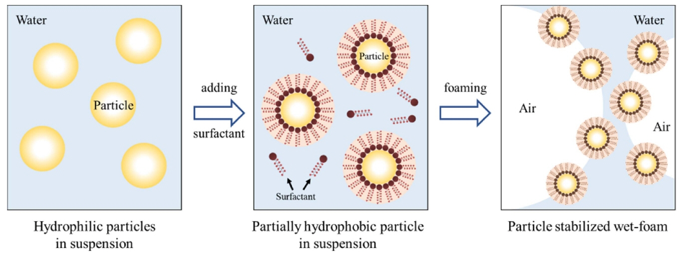
In this review, the direct foaming technique relies on the use of surfactants or particles to stabilize a foam generated by mechanical frothing or bubbling of a gas through a suspension. Direct foaming produces porous materials by the incorporation of air into a suspension or liquid medium. The foam structure is then set by high-temperature sintering to obtain crack-free, high-strength porous ceramics. The suspensions are stabilized in situ through the hydrophobization of the suspended particles by short chain amphiphilic molecules, as shown in Fig. 2.2,4,95,96) The coated hydrophobic particles irreversibly adsorb to the air-water interface, thus stabilizing it.4,97,98) These wet foams can remain stable for several days, and show no bubble coarsening, drainage, coalescence, or Ostwald ripening. The short-chain amphiphiles modify in situ the wetting behavior of the particle surfaces, as in a Pickering emulsion. For example, coalescence can only be hindered by providing electrostatic or steric repulsive force sufficiently strong to overcome the attractive van der Waals forces. This can be imparted by surfactant molecules or particles attracted to the air-water interface.2) Furthermore, the wet foams can be controlled to efficiently prevent drainage and coalescence pores, and they can also prevent resistant long-term Ostawald ripening defects. Ultra-stable wet foams can be produced by direct foaming, using particles instead of surfactants as foams stabilizers. 34,35,37,47,99-102) Fig. 3 shows the processing routes of direct foaming method.
Therefore, porous ceramic properties are also highly influenced by their chemical compositions and microstructures, with porosity, pore morphology, and size distribution being tailored by different compositions, different physical structures of the starting materials, and the use of different amphiphiles.47,103-105)
3. Destabilization of Colloidal Suspension
The mechanism of collapsing foam from colloidal suspension and wet foam stability is at the micro-scale, involving what is happening between the bubble boundaries, as well as the adjacent bubbles. This nanometer-to-millimeter scale region will be the focus of the foaming stability research presented in this review. The total porosity of directly foamed ceramics is proportional to the amount of bubbles incorporated into the final suspension or liquid medium during the foaming process. The pore size, shape, and distribution are determined by the wet foam stability before the sintering process. Particle-dispersed liquid foams are thermodynamically unstable, due to their high gas-liquid interfacial area. Several physical processes take place in the wet foam to decrease the overall system free energy, leading to foam destabilization. The main destabilization mechanisms are drainage (creaming and sedimentation), coalescence, and flocculation, as shown in Fig. 4.
Creaming and sedimentation are caused by the effect of gravity: lighter particles float, while heavier particles settle. These effects are reversible, in that mechanical agitation (homogenization or simple shaking) will re-disperse the suspension. Coalescence and flocculation are not reversible, and so affect a suspension’s stability. Flocculation is the clustering of colloidal particles via attractive van der Waals forces. It can be overcome or prevented by higher-energy ultra-sonification, or by generating particles with repulsive interactions.106) Coalescence is the greatest destabilizing mechanism. It involves smaller particles collapsing into each other, forming larger particles with different properties. Many dispersion techniques have been developed to prevent coalescence inside the bubble getting larger in number. 107,108,164)
Several physical processes can occur to decrease the overall free energy and destabilize the foam.36) Drainage occurs through gravity; light gas bubbles rise, forming a denser foam layer, while the heavier liquid phase is concentrated below. Coalescence takes place when the thin films formed after drainage are not stable enough to keep adjacent cells apart. Their collapse results in the joining of neighboring bubbles. The stability of the thin films is therefore described in terms of attractive and repulsive interactions between the bubbles. Van der Waals forces drive the bubbles closer. These forces can be overcome by electrostatic forces, steric repulsion forces, or ligand exchange reactions. Surfactant or particles adsorbed at the air-water interface can also reduce the van der Walls forces.2,22,109) Ostwald ripening or disproportionation is another destabilizing effect that is more difficult to overcome. This occurs due to differences in the Laplace pressures between bubbles of different sizes. The Laplace pressure inside a gas bubble arises from the curvature of the air-water interface.
4. Stabilization of Colloidal Suspension
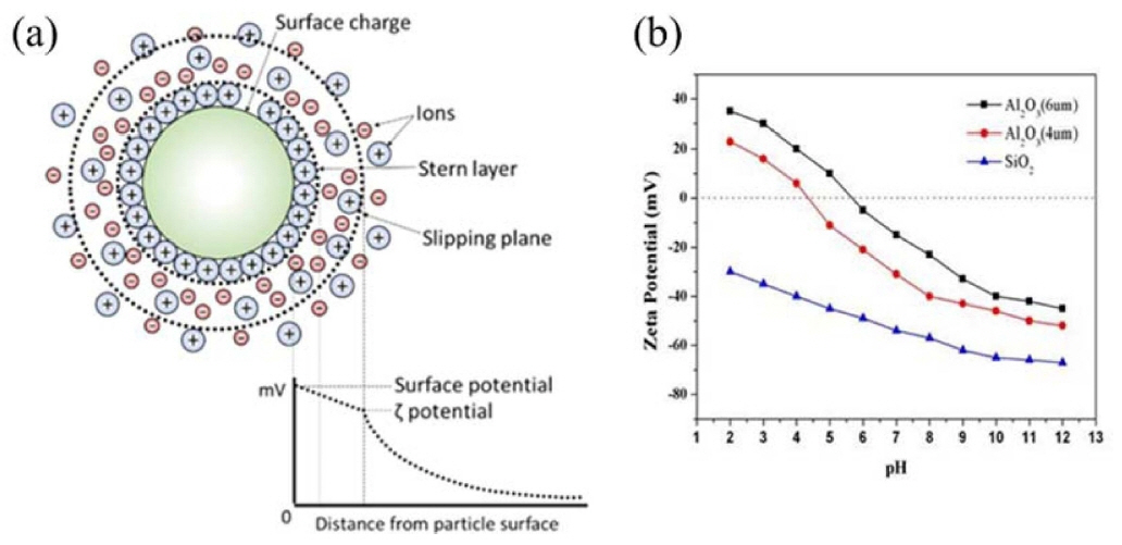
In the direct foaming process, instability of the wet foam from the colloidal suspension arises due to their high gasliquid interfacial areas, which raise the free energy of the system. To achieve a stable system, free energy must be minimized. The electro kinetic properties of a colloidal system can be described using the zeta potential. Higher charges on the particle surfaces stabilize a colloidal suspension by preventing the particles from coming into contact and coalescing.110,111) In the electrostatic stabilization mechanism, the charged particles develop an extended layer of similar charged ions in aqueous colloidal suspension, which is known as an electrical double layer. The repulsion force develops when there is an overlap between charged layers, thus particles remain separated. As the concentration of oppositely charged ions in the aqueous medium increases, the range of the electrical double layer interaction decreases, due to the screening affect brought about by the excess ions (oppositely charged) in the continuous medium. This ultimately causes particle agglomeration. On the other hand, steric stabilization is effected by adsorption of polymeric additives to develop protective colloids on particle surfaces. This results in effective repulsion rendered by the extended polymer layers in the continuous liquid medium, as shown in Figs. 5(a) and (b). The combination of the two mechanisms (electrostatic and steric) in dispersing the particles is called the electrosteric stabilization mechanism.112)
5. Properties of Colloidal Suspension
5.1. Zeta potential
The adsorption of surfactants from the aqueous medium onto the surface of particles can be driven by electrostatic interactions between the particle surface charge and ionized molecules, or specific chemicals between the molecule and the surface hydroxyl groups. In the case of oxides exhibiting predominantly positive or negative charges on the surface, the electrostatic adsorption of amphiphilic molecules is a convenient approach for surface hydrophobization. For example, protonated amines and deprotonated carboxylic acid groups can be used for the surface modification of oxides exhibiting low and high isoelectric point (IEP), respectively.113) In order to extend this approach to different types of inorganic particles, amphiphilic molecules have to be deliberately selected that exhibit a short hydrophobic tail combined with a head group that is able to adsorb on each specific particle surface. Therefore, the choice of the amphiphile head group highly depends on the surface chemistry of the particle involved.110) In general, colloid suspensions with high zeta potential (negative or positive) are electrically stabilized, while colloids with low zeta potentials tend to coagulate or flocculate (Fig. 6(a)). Zeta potential shows as key indicator of the stability of colloidal dispersions, as illustrated in Table 1. A suspension’s pH affects its charge distribution, and hence its zeta potential. The IEP is the pH at which a colloid’s zeta potential is zero, and it can be used to derive information about the pH ranges in which a colloid is stable. A suspension’s pH can be modified to allow dissociated surfactant to adsorb electrostatically as counter ions onto oppositely charged alumina hydroxyl surface groups.114) The suspension’s inorganic particles can be stabilized in situ by the particles’ hydrophobization with different colloidal particles containing predominantly -OH2+, -OH, and -O- surface groups. Surfaces with predominantly -OH2+ and -OH groups can be achieved on inorganic alumina particles at pH (4.5 and 9.5), respectively. This could be derived from the zeta potential data for bare Al2O3 particles, which confirm that the surface exhibits mainly -OH2+ (positive net charge) and -OH (neutral net charge) groups under those conditions.115) Stable colloidal suspensions are widely employed in wet ceramic forming techniques, including slip casting, tape casting, pressure casting, centrifugal casting, and direct foaming process.2,20) In those foaming techniques, the colloidal processing is an important tool in achieving the stable suspension involving the dispersion of particles that influences the succeeding forming steps. Furthermore, slurries or suspensions are effectively dispersed by electrosteric stabilization mechanisms to allow the dispersion of particles at high solid loading with minimum viscosity.116) Fig. 6(b) shows zeta potential of Al2O3 and SiO2 colloidal particles.
5.2. Rheological properties
Success in achieving the desired physical properties of different types of porous ceramics relies on the critical application of the colloidal forming techniques. In all types of suspensions, the rheological properties of the concentrated colloidal suspension play a significant role in controlling the shape forming behavior and optimizing the properties of the green body.117,118) It involves the manipulation and control of the inter-particle forces in particle dispersed suspension, in order to remove heterogeneities, and to optimize the suspension properties. These optimum properties of colloidal suspension are basically governed by the interaction of attractive and repulsive forces. The net effect of these forces acting on particle surfaces determines the state of dispersion of the colloidal suspension, wherein the repulsive forces are maximized to counteract the formation of attractive forces that cause particle agglomeration. This repulsive barrier can be achieved by electrostatic or steric stabilization mechanisms, which depend on the liquid medium and the composition of the powder.117,119,120) Therefore, special effort is inevitable for the control of defects and to tailor the microstructure of wet foams. The physical properties of colloidal systems depend on the viscosity of the liquid, the amount of solids, the size distribution of the solids, and interactions between the solid particles, and between the solid and liquid. The rheological properties of a ceramic suspension are controlled not only by the type of deflocculant used in the process, but also by surfactants, foam agents, water hardness, surfactant, pH, and the characteristics of the raw materials.121-123)
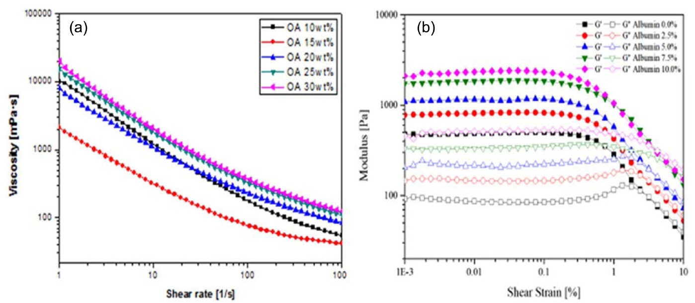
The viscosity of the colloidal suspension increases as the surfactant concentration added to the colloidal suspension increases with an increase in shear rate. However, the suspension with higher surfactant concentration shows higher viscosity for all ranges of shear rates, and this is attributed to the considerable effect of the adsorption free energy, as shown in Fig. 7. Adsorption free energy is always present in a colloidal system,124,125) and the addition of a surfactant concentration leads to a considerable increase in viscosity as the adsorption between the particles increases. The flow curve illustrates that all suspensions exhibit a typical shear thinning behavior with decreasing viscosity and increase in shear rate, as shown in Fig. 7(a). This shear thinning behavior can be observed at low shear rates where the surface forces between particles dominate the rheological behavior.126) As the surfactant concentration and, the viscosity of the suspension increases with the increase in solid content, the mechanical strength of the porous ceramics are enhanced.
Figure 7(b) shows the storage and loss modulus analyzed with varying shear strain, with amplitude sweep measurement in the oscillation mode of the SiC slurry with different albumin content. The amplitude sweep of the strain vs modulus, the section for the linear storage modulus (G′), LVE range, and limiting value of the LVE range are selected where the storage modulus begins to decrease. The storage modulus (G′) was measured to be linear, and to decrease at the shear strain, due to the material′s internal structure breaks. All the results have intersections (G′ < G″) at storage modulus (G′) and loss modulus (G″), and after this intersection, the viscous properties become stronger. Therefore, as shown in Fig. 7(b), as the amount of foam agent increases, the air content decreases. However, the internal structure becomes relatively hard, due to the viscosity increases.127,128)
6. Evaluation of Particle-stabilized Wet Foam
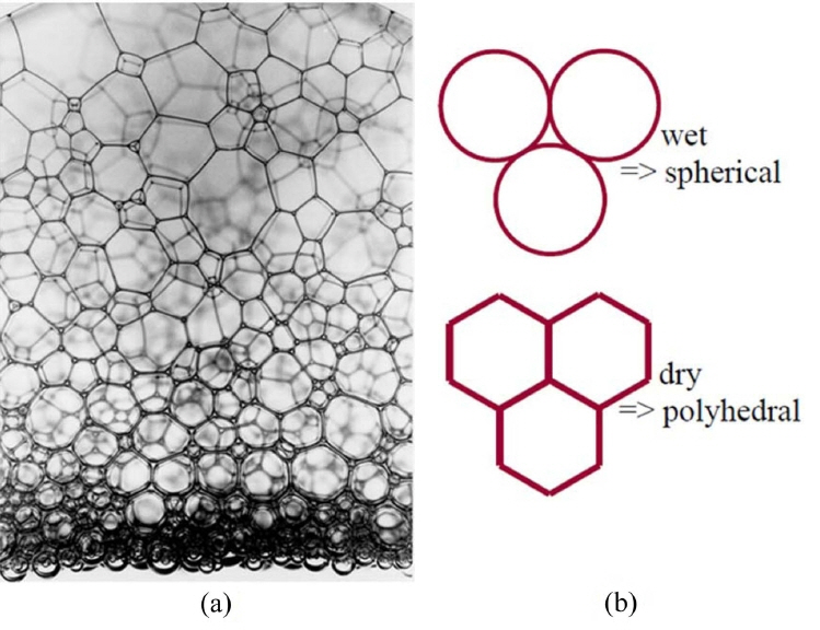
Wet foam derived by direct foaming is defined as a three-phase system, in which gas cells are enclosed by particle-stabilized colloidal suspension. The thin films junctions with 3 or more bubbles are plateau borders, and the face of the film between 2 bubbles is a lamella. The shape of the foam bubble is dependent on the volume of solid, liquid, or gas within the foam. In this paper, the amount of gas in the foam (volume fraction) is generally between (50 and 95)%, and bubbles will deform each other when the volume fraction is above 80%.129) Progression from a wet foam to a dry foam is depicted by a change in bubble shape in the case of a two-phase system in which air bubbles are enclosed by liquid phase, as shown in Fig. 8 below. As the liquid drains out, the bubbles coalesce, and the foam becomes more polyhedral along the plateau borders. The polyhedral shape of the foam is based on fluid draining from the bubble walls to vertex.130,131) Pressure differences between the bubble walls and vertex drive the fluid flow direction. The radius of curvature of the bubbles along the walls creates the pressure differential.132,133)
Although the goal of this review is to understand how to reduce the destabilization of wet foam from particle-stabilized colloidal suspension, there is more fundamental understanding of how surfactants stabilize foams. The stability of a bubble or foam depends on multiple components that affect surface energy.130,151) Film elasticity is a stabilizing mechanism that allows the film to figuratively self-heal. Imagine an air-water-air film as shown in Fig. 5(b) above. Within the liquid are surfactants that have hydrophilic and hydrophobic ends. The surfactants arrange at the interfaces, depending on their affinity for water. If an applied force or stress creates a thin spot on the bubble surface, there will be an increase in the surface area and tension. With an increase in surface area, the concentration of surfactant at the interface is decreased as well. These gradients will initiate the process of the surfactants to transfer toward the thinned spot. As the surfactants transfer to the area of lower concentration, they will bring along the underlying layers of liquid. The resultant fluid flow restores/repairs the thinned spot. The self-healing process is only possible if a surfactant is present, and therefore, pure liquids will not foam.130) The concentration of the solute in solution can also affect the film elasticity. At low concentration, the solute has a limited role, and may not stabilize the foam, due to marginal increase in film elasticity. On the other hand, at extremely high concentrations, the diffusion rate can be so rapid that stabilizing mechanisms can be eliminated.131-134)
6.1. Contact angle and surface tension
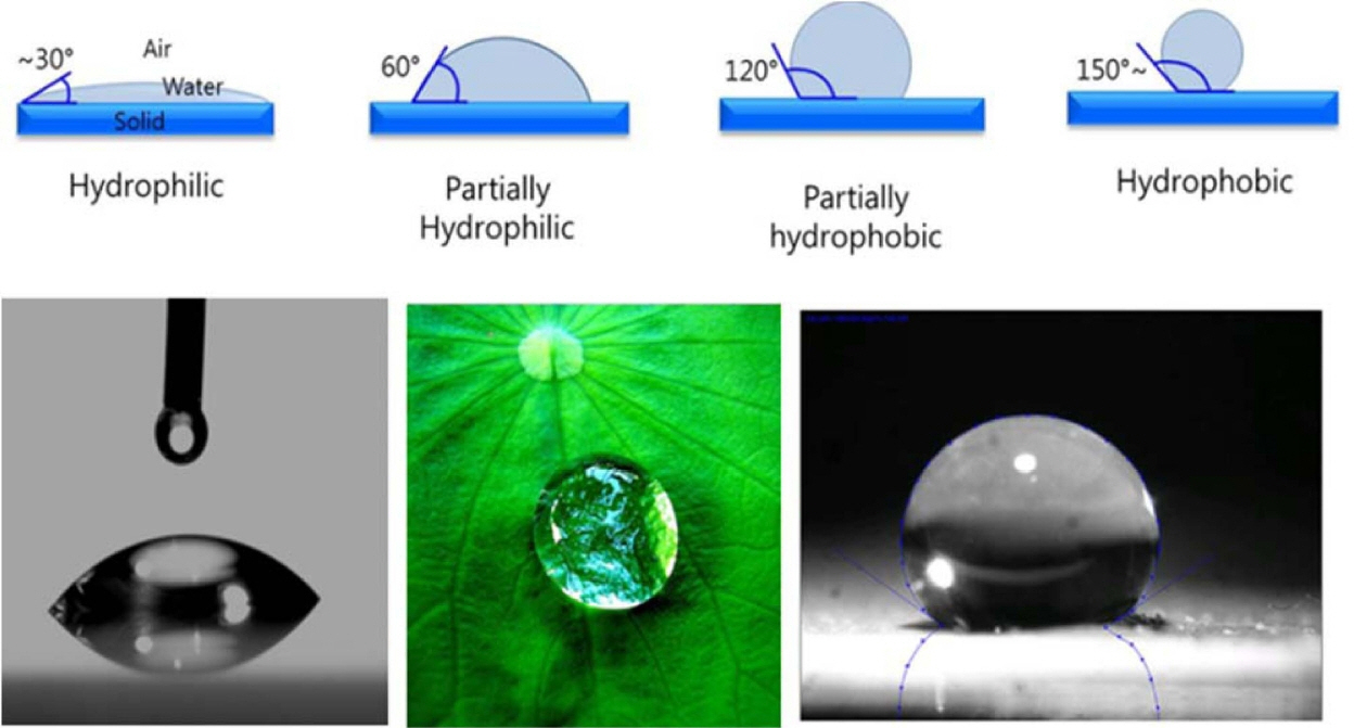
After the stabilizing effects of zeta potential and pH, contact angle and surface tension are important determinants of colloidal systems. Once a suspension is stabilized, the degree of hydrophobization is the main property that affects the production of foam. Given their thermodynamic instability, foams are often kinetically stabilized through the adsorption of surface-active molecules or colloidal particles at the gas-liquid interfaces.2,12,135) The adsorbed molecules and particles stabilize the system, by inhibiting the coalescence and Ostwald ripening of droplets and bubbles. Adsorption at the fluid interfaces occurs when particles are not completely wetted by any of the fluids, thus exhibiting a finite equilibrium contact angle at the triple phase boundary, as shown in Fig. 9.28,36,49,136)
The equilibrium contact angle (θ) is determined by the balancing of the interfacial tensions. A decrease in surface tension upon increasing the initial amphiphile concentration can be observed. However, above a critical amphiphile concentration, surface tension decreases sharply. Above this critical amphiphile concentration, the particles are sufficiently hydrophobic at the air-water interface, and decrease surface tension more greatly than that expected from free amphiphiles alone.53,114,137) This significant reduction in surface tension upon particle adsorption is caused by a decrease of the total area of the highly energetic air-water interface. Similar surface tension effects have been observed in systems employing various amphiphiles.4,105)
Controlling particle contact angles at the interface is important, as it determines their wettability (Fig. 9). Furthermore, tailoring particle contact angles via modification of chemical composition enables the creation of foams with a variety of functionalities.138,139) Contact angle depends on surface chemistry, roughness, impurities, particle size, and the composition of the fluid phases. Metallic and ceramic particles can achieve any contact angle (0 < θ < 180)° by reacting or adsorbing hydrophobic molecules on their surfaces. 2,22,28,36) The use of short amphiphiles to tailor particle wettability is a general and versatile approach for the surface modification of a wide range of ceramic and metallic materials.2,4,48,114)
6.2. Adsorption free energy
The foams require the adsorption of particles on the surfaces of air bubbles upon their formation. Al2O3 particles can be hydrophobized by modification with short-chain carboxylic acids: the carboxylate groups adsorb to the alumina’s surface,40,139) leaving the hydrophobic tail in contact with the aqueous solution. This has been shown to stabilize the dispersion.41) The hydrophobicity imparted by the first layer of de-pronated amphiphiles adsorbed onto the surface leads to an energetically unfavorable exposure of hydrophobic species to the aqueous phase. This favors the adsorption of additional molecules from the aqueous phase onto the particle surfaces to decrease the system’s free energy, which determines the stability of a suspension or wet foam. Particles attached to foam and mist gas-liquid interfaces lower the overall free energy by replacing part of the interfacial area, rather than reducing the interfacial tension, as in the case of surfactants.129,140) The energy of attachment, i.e. the Gibbs free energy (G), gained by the adsorption of a particle of radius r at the interface can be calculated using simple geometrical arguments that lead to the following equation: Fig. 10(a) shows the predicted energy of particle attachment G and surface free energy as a function of the contact angle for three different particle sizes.
where, ‘θ’ is the contact angle, and γLG is the gas-liquid interfacial tension. While the maximum energy gain can only be achieved at θ = 90°, contact angles as low as 20° can yield attachment energies in the order of 103 kT in systems of 100 nm particles.2,141,142)
The high energy associated with the adsorption of particles at interfaces contrasts with the low adsorption energies of surfactants and leads to foams stabilized by particles being more stable than those stabilized with surfactants. It also leads to steric layers, which strongly hinder bubbles’ shrinkage and expansion, minimizing Ostwald ripening for very long periods of time.28,143,144) The particle systems described in Fig. 4 had adsorption achieved by ligand exchange, whereby a surface hydroxyl group was exchanged for another group. This occurred because of the favorable change in the surface charge by the removal of (OH2+), a better leaving group, and replacement with (-OH).43,44)
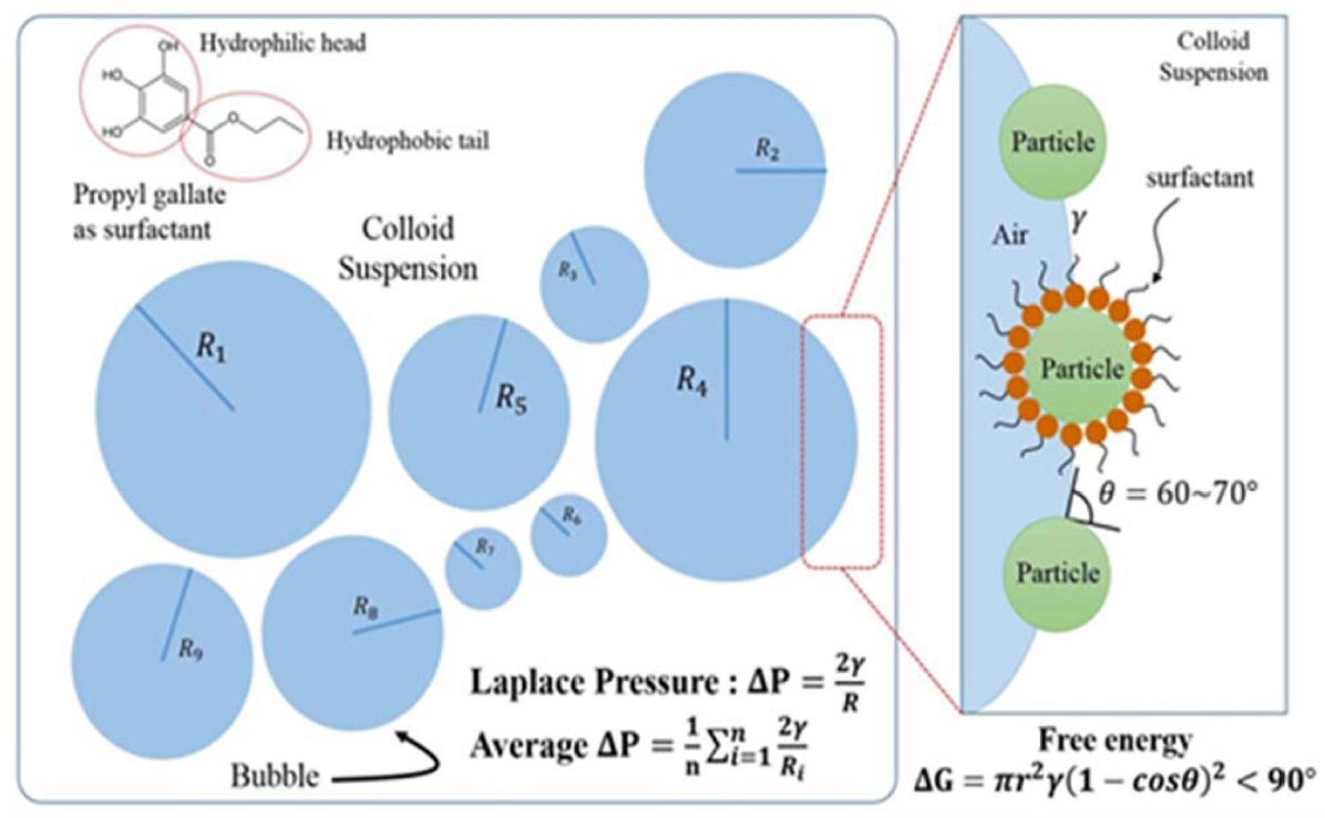
6.3. Laplace pressure
The Laplace pressure (N/m2) is the pressure difference between the inner and outer side of a bubble or droplet. For a spherical bubble of radius R and gas-liquid interfacial energy γ, the Laplace pressure ΔP is given by 2γ/R (Fig. 11). The pressure and force generated for the stabilization can also be calculated through the measurement of bubbles at the intersection. This ΔP can be calculated by the equation given below:
The difference in the Laplace pressure between bubbles of distinct sizes (R) leads to bubble disproportionation and Ostwald ripening, because of the steady diffusion of gas molecules from smaller to larger bubbles over time. This process can be slowed by using surfactants or particles adsorbed at the interface, which decrease the interfacial energy.15,104,105) Wet foam stability is also related to the degree of hydrophobicity achieved from the surfactant, which replaces part of the highly energetic interface area, and lowers the free energy of the system, leading to an apparent reduction in the surface tension of the suspension. 36,140,145) Stability also depends on surface charge screening, the electrical diffuse layer around a particle surface not being sufficiently thick to overcome the attractive van der Waals forces between particles. Overcoming the van der Waals attractions requires a stable hydrophobizing mechanism. 146) The combined effects of these actions may collapse the foam within a few minutes after air incorporation. Foam life times have been increased from several hours to days and months by the adsorption of the short chain amphiphilic molecules,4,50) while stabilization for only a few minutes or hours results from the use of long-chain surfactants or proteins at the air-water interface.15,36) Unlike other particle-stabilized foams,2) these foams percolate throughout the whole liquid phase, and exhibit no drainage over days and months,147,152) due to the high concentration of modified particles in the initial suspension, which allows for the stabilization of very large total air-water interfacial areas.148)
7. Foaming and Characterization
Foaming of the final suspension was carried out in room temperature (RT), using a household hand mixer (150 watt, Super Mix, France) at highest power, for 15 minutes. The mechanical frothing facilitates air incorporation throughout the whole volume of suspension. The air content was measured, by calculating the percentage of volume increase of the suspension after foaming.
where, Vwet foam indicates the wet foam volume after foaming, and Vsuspension indicates the volume of suspension before foaming. The average wet bubble size was measured by analyzing optical microscope images using the software linear intercept (TU Darmstadt, Germany). The optical microscope (Somtech Vision, South Korea) in transmission mode was connected to a digital camera. For each sample, a minimum of 100 bubbles was evaluated. The most critical issue in direct foaming methods is the approach used to stabilize the air bubbles incorporated into the suspension. In this review, propyl gallate, propionic acid, butyric acid, and valeric acid for Al2O3 and ZrO2, and hexylamine for SiO2 and SiC were used as a surface modifying agent, which imparts hydrophobicity to the particle surface, and thus improves foam stability, respectively. To investigate the wet foam stability, the wet foam samples were filled into cylindrical molds of constant volume and left for 48 h. Foam stability was evaluated upon observing the percentage of volume loss of the foam.149,150)
where, VFinal indicates the volume of wet foam after 48 h, and VInitial indicates the volume of wet foam before 48 h.
8. Wet Foam Stability
The stabilities of the wet foams obtained by Kim and Gauckler resulted from the different stabilization mechanisms of the air-water interface from those applied in the conventional shaving foam. Generally, ceramic particles can achieve any contact angle by reacting or adsorbing hydrophobic molecules on their surfaces, as adsorption depends on surface chemistry, roughness, impurities, particle size, and composition of the fluid phases.9,146) The wet foam stability from particle-stabilized colloidal suspension can be determined by observing the average bubble size with respect to time after foaming. We can attribute the first two cases of remarkable resistance to the irreversible adsorption of the partially hydrophobized particles at the air-water interface. Therefore, the bubble sizes show to be of medium size, giving higher strength to the thin film at their interfaces. The foams stabilized with different additives are prone to bubble coarsening, due to the pressure difference between two bubbles of different radius, which leads to Ostwald ripening.2,4,13) This thermodynamically driven spontaneous process occurs because the internal pressure of a particle is indirectly proportional to the radius of the particle. Large particles, with their lower surface-to-volume ratio, result in a lower energy state, whereas the smaller particles exhibit higher surface energy. As the system tries to lower its overall energy, molecules on the surface of a small particle tend to detach. They diffuse through the colloidal solution and attach to the surface of larger particles. Therefore, the number of smaller particles continues to shrink, while larger particles continue to grow.152)
Table 2 summarizes the physical properties of colloidal suspension with the wet foam stability above 80%. Those with the addition of SiO2,4,25,41) TiO2,103) SiO2-TiO2,24,50,97) and TiO2-ZrO220) content in Al2O3 colloidal suspension produced lower adsorption free energy due to the higher inter-particle attraction, increasing the viscosity. Also, contact angle of around 60°-70° for the Al2O3 colloidal suspension leads to better wet foam stability, and can give surface of 21-33 mN/m. The required partial hydrophobization of the particles occurs at this point, which leads to porous ceramics with higher porosity. Table 1 shows the relationship between adsorption free energy corresponding to the concentrations of different chain length of amphiphile that has been established. Stable and unstable zones have been described relating to the data obtained by the wet foam stability. High adsorption free energy of 1.3 × 10⁻¹² J to 6.9 × 10⁻¹⁵ J of the initial Al2O3 suspension without additives foam as stabilizer results from the spontaneous bubble growth, leading to foam instability. Whereas, higher adsorption free energy of about 1.3 × 10⁻¹³ J to 1.6 × 10⁻¹² J at the interface results in irreversible adsorption of particles at the air-water interface, which leads to outstanding stability. The calculations show that the energy level decreases with the nanoparticle size, and with increase in SiO2 content. However, after the middle value 0.75 of the SiO2 loading, the van der Waals attraction force between the particles gradually increases, forcing the suspension to destabilize, and finally decreases the wet foam stability from 87% to 68%. A higher energy of adsorption of 7.07 × 10⁻¹³ J could be achieved in the initial suspension without SiO2 content. The adsorption free energy decreases with the increasing concentration. Higher contact angles of 62° to 75° with a lower interfacial energy of 7.07 × 10⁻¹³ J were seen at SiO2, TiO, and ZrO2 mole ratios of 0.25, giving an interfacial tension of 42 mN/m.152)
The Laplace pressure of all evaluated suspensions has been plotted in a graph with respect to the various concentrations of different chain length of amphiphile. As can be seen, the instability occurs when the Laplace pressure is too low, as in the case of 0.10 mol/L of amphiphile concentration. 4)
Wet foam stability occurs when the Laplace pressure is about 0.8 to 1.4 mPa. Valeric acid, having the longest chain length, exhibits high Laplace pressure, resulting in the outstanding stability of wet foam.55,84) The Laplace pressure increases with the increase of the additive contents. This behavior can be attributed to the fact that high additive content requires large volume of water in the suspension, which subsequently lowers the outer pressure of the bubble. The wet foams were stable at the pressure difference between 20 and 25 mPa, which corresponds to the SiO2, TiO2, and ZrO2 mole ratio content of 0.52 to 1.31, were reported, respectively. This is due to the decrease in surface tension and increase in foam viscosity that result from higher particle concentrations. This reduces the resistance of air bubbles against rupture, and thus leads to the production of foams with average bubble sizes.153,154)
8.1. Al2O3 based porous ceramics
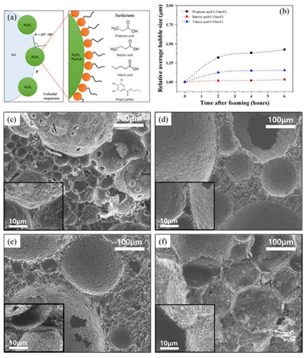
The anchoring group of the molecules attaches to the particle surface and promotes the surface hydrophobization of colloidal particles.4,25,41) The amphiphiles used here adsorb onto the Al2O3 surface through electrostatic interactions between the positively charged surfaces and negatively ionized amphiphilic molecules. Surface modification of particles using these amphiphiles was carried out at a pH close to the molecule’s pKa values. At this condition, approximately half of the amphiphilic molecules are present as ionized form, and are thus easily adsorbed on the oppositely charged particle surface.2,126,134,151)
Furthermore, the air content bubble size, and bubble size distribution of wet foams used to produce Al2O3 porous materials also have a remarkable influence on the final mechanical and physical properties of porous solid structures (Fig. 12).152,153) Particles with high aspect ratio and/or that exhibit hysteresis of the contact angle are particularly efficient in preventing bubble/droplet coalescence. However, the stability to resist Ostwald ripening has been explained by the mechanical resistance of the outer particle layer to the shrinkage and/or expansion of droplets and gas bubbles. The high stability rendered by the particles adsorbed on the surface of the droplets and bubbles is a key feature in the preparation of tailored microstructure of materials from foams.154) The degree of particle hydrophobization achieved through the surface adsorption of amphiphiles has been investigated with the assistance of surface tension measurements. A decrease in the surface tension upon an increase of the initial amphiphile concentration in the solution has been observed for all evaluated suspensions. However, above a critical amphiphile concentration, a relatively strong decrease in the surface tension has been observed.126,134,155) Above this critical amphiphile concentration, the particles were sufficiently hydrophobic to attach to the air-water interface, leading to a more pronounced decrease in the surface tension, than that expected from the free amphiphiles alone. This significant reduction in surface tension upon particle adsorption was caused by a decrease of the total area of the highly energetic air-water interface.156) Fig. 10 shows that the average bubble size decreases with increasing amphiphile concentration and particle hydrophobicity. This is due to a decrease in surface tension and an increase in foam viscosity, because of higher amphiphile concentrations. This decreases the resistance of air bubbles against rupture, and thus leads to the production of foams with average bubble sizes. It is interesting to note that the Valeric acid, having the longest amphiphilic chain, produces very small sized bubble of about 35 to 25 μm. This can be attributed to the greater hydrophobicity, which results in the enhanced stability of particle stabilized foams against bubble coalescence and Ostwald ripening, as shown in Fig. 12 b).
8.2. SiO2 based porous ceramics
The SiO2 particles get partially hydrophobized with the addition of Hexylamine, an amphiphile, with optimized chain length as shown in Fig. 13(a). The negatively charged surfaces of silica particles get coated with the positively charged hydrophobic end of Hexylamine, making the molecule partially hydrophobic, and leading to the stabilization of the foams in the wet state. The average contact angle of the d50 - 3.5 μm SiO2 suspension increased with the increase in SiO2 content.157) In Fig. 13(b)-(d), the suspensions with content between 25 and 30 vol.% of SiO2 were found to be highly stable with a higher level of surface tension, resulting in highly stable foams to sintered porous ceramics. It can also be proved that the contact angle of around (73-77)° for micro-particle suspension leads to better wet foam stability, and this further increase by micro-particle suspension can give a surface tension of (40-47) mN/m. The wet foam stability maximum of around 80% was established to correspond to the particle’s free energy of 8.32 × 10⁻¹³ and 1.04 × 10⁻¹² J at a particle concentration of around (25-30) vol.%. The microstructures prove the decrease in pore size with the increase in particle concentration, as well as Ostwald ripening, is seen in the 35 vol.% concentration, where the bubbles are found to agglomerate.25,98,158)
8.3. ZrO2 based porous ceramics
The average contact angle of the ZrO2 suspension decreased with increasing TiO2 content, because the contact angle was measured at the solid/liquid interface. As the molar concentration of the TiO2 particles were increased to a 1:0.50 mole ratio, the related increase in the viscosity of the suspension led to a gradual decrease in the contact angle of the suspension. However, with a further increase in the mole ratio, the contact angle was found to gradually increase. Therefore, the most stable wet foams were found to be formed at a mole ratio of 1:0.50 at around 54°. Moreover, the surface tension of the suspension (the contractive tendency of the outer surface of the liquid) increased with increasing molar ratio of TiO2, and its highest value was found to be 76 mN/m, at which the wet foams were considered to be the most stable.159) This stabilization point, which corresponds to the wet-foam stability of sintered porous ceramics and can be obtained by adjusting the solid content of the suspension, is directly related to a free energy of about 9.2 × 10⁻¹² J, and to a Laplace pressure in the range (2.0 - 2.2) mPa. A wet foam stability of around that was established at a mole ratio of 1:0.50, which can be considered to be the most stable zone, corresponding to a fine porous microstructure. The XRD patterns show an increase in the ZrTiO4 content with increasing mole ratio of TiO2.30,96,160) In Fig. 14(b), the bubble size decreased gradually from (140 to 80) μm with increasing mole ratio of TiO2 in the colloidal suspension from (0.25 to 0.50). The bubble size increases gradually with further increases in the mole ratio of TiO2. Similarly, the pore size decreases gradually with increasing TiO2 content, and then gradually increases with further increases in the TiO2 content in the colloidal suspension. The bubble sizes and the pore sizes of the wet and the dry foams were found to be (80 and 60) μm, respectively and at the mole ratio of 1:0.50 of ZrO2 to TiO2, for which the wet foam stability was highest.
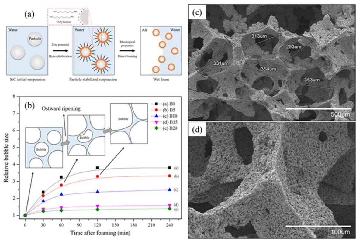
8.4. SiC porous ceramics
To stabilize the wet foam, an initial colloidal suspension of SiC was partially hydrophobized by the surfactant octylamine (12.5 wt.%), as shown in Fig. 15. The results show a wet-foam stability of more than 95% that corresponds to an air content of 87.8%, an increase of the adsorption free energy from (3.0 to nearly 7.5) × 10−5 J, a Laplace pressure increase from (0.16 to 0.20) mPa, and a relative bubble size of 1.3 for the colloidal particles with a 20 wt.% binder content. 95) The uniform distribution of the highly open/interconnected pores could be controlled with thick struts and an increase of the binder content up to 20 wt.%, leading to the achievement of a higher-stability wet foam with respect to the porous ceramics. Fig. 15 shows the relative-bubble-size time frame of 250 min, where the bubbles tended to collapse after 1 h, due to the effect of the Ostwald-ripening destabilization mechanism that leads to the steady growth of the bubble size, thereby resulting in an unstable wet foam. The SiC colloidal suspension without the binder shows the maximum relative increase of the bubble size after 2 h. The bubbles with the binder contents of 5 and 10 wt.% exhibited the higher increments of the relative bubble size with respect to the binder contents of 15 and 20 wt.%, whereas the binder contents of 15 and 20 wt.% are considerable, with a nearly constant relative bubble size. Also, for the corresponding solids loading and binder content, a minimum pressure difference between the bubbles of different sizes is necessary to ensure the stability of the foam, and to overcome defects, such as coalescence and drainage.122) Furthermore, it can also be chemically modified for specific catalytic applications through the addition of promoters (oxides like SiO2, Al2O3, TiO2, ZrO2, carbides, and metals), rendering the fabrication simple and cost effective.161,162) A novel method was developed by Liu et al. to produce the pure silicon carbide foams via the high-temperature recrystallization with the presence of a novel foaming agent-SiO2,158) and also three-dimensional (3D) mesoporous SiC samples with highly ordered porosity were prepared using three different routes by Zorko et al..163)
Table 3 shows the bubble size of the suspension and the pore size by thin film or struts formed after the foaming of the particle stabilized suspension and sintering. The average bubble size for these types of stabilized foams was 98 to 140 μm. The required partial hydrophobization of the particles occurs at this point, which leads to porous ceramics with porosity greater than 80% and pore size of about 108 μm after sintering at 1,500°C for 1 h. The average bubble size decreases with increasing amphiphile concentration and particle hydrophobicity. This is due to the decrease in surface tension and increase in foam viscosity because of higher amphiphile concentrations. This decreases the resistance of air bubbles against rupture, and thus leads to the production of foams with average bubble sizes in the range 95-136 μm in pure Al2O3 porous ceramics. It is interesting to note that the valeric acid, having the longest amphiphilic chain, produces very small sized bubbles of about 35 to 25 μm.
Table 3 also establishes the air contents and foam stability of Al2O3-TiO2 equi-molar suspension, with respect to different vol.% of 3:2 mole ratio of Al2O3-SiO2 suspension added for the mullite phase.50,97) High-volume foams with air content up to 83% form upon mechanical frothing, which strongly indicates the stabilization of air bubbles, due to the attachment of particles to the air-water interface. This is probably due to the high viscosity of the suspension and higher particle concentration.
The hierarchical structures of porous ceramics show open and interconnected pore structure, due to the drainage effect of liquid within bubble walls during the dry processing. These structures have well-developed and narrow size distribution with porosities up to 80% from larger to smaller pores and thick struts (films in wet foams).164) This leads to the production of more stable foams sintered to form porous ceramics. It is interesting to note that at the same concentration of amphiphile, the shortest chain carboxylic acid, i.e. Propionic acid, produces relatively larger pore size than the longest chain carboxylic acid i.e. Valeric acid.152) This can be attributed to the fact that greater hydrophobicity is achieved with the aid of the long carbon chain present in Valeric acid, which results in small and uniform pore size. The smaller cell sizes result from the high stability of the foams in the wet state, which impedes bubble coarsening.
9. Conclusions
Porous ceramic microstructures and properties are affected by their method of synthesis in different systems, such as Al2O3, Al2O3-SiO2, Al2O3-TiO2, Al2O3-SiO2-TiO2, Al2O3-TiO2-ZrO2, Al2O3-TiO2-SiO2-ZrO2, SiC-SiO2, and SiC, which are discussed. Particles stabilize wet foams by causing steric hindrance to the coalescence of bubbles, and by modifying the colloidal properties of the interfaces. The interface-contact angle stability of ceramic foam is directly related to the surface energy of the colloidal suspension, which corresponds to the calculation of free energy and Laplace pressure for wet foam stability to porous ceramics. The hierarchical interconnected pore structure of sintered ceramics can be tailored by adjusting the concentration of the amphiphile, and also by modifying their chain length. An increase in the chain length of the carboxylic acid used as amphiphile and their concentration leads to foams with smaller average bubble size, due to the decrease in surface tension, and higher hydrophobicity. The effects of surface tension and contact angle on foam stability are depicted, and a stabilizing zone is obtained. Using this simple and versatile approach, it is possible to tailor the foam characteristics, which will eventually open new ventures in various application areas of porous ceramics. The pores produced by this method result from the direct incorporation of air bubbles into a ceramic suspension, eliminating the need for pyrolysis before sintering. Cellular structures prepared by direct foaming are generally stronger than those prepared by replica synthesis, due mainly to the absence of flaws in the cell struts. Given the importance of the chosen synthetic method, this review examines currently available processes for forming porous ceramics. Direct foaming is a simple and versatile process for the low-cost manufacture of porous ceramics for various applications. From the collected results, we found that microporous structures with pore sizes from 30 μm to 570 μm and the porosity within the range from 70% to 85% have been produced for a number of well-established applications, such as catalysis, refractory insulation, and hot gas filtration. Continuous study will result in further improvements to its mechanical testing method, and wider applicability of its products. This review reflects that with the addition of different additives, the porous ceramics can achieve higher stability.