Kim, Lee, Oh, Kim, Jang, and Kim: Characteristics of Bulk and Coating in Gd2−xZr2+xO7+0.5x(x = 0.0, 0.5, 1.0) System for Thermal Barrier Coatings
Abstract
Gadolinium zirconate, Gd2Zr2O7, is one of the most versatile oxides among the new thermal-barrier-coating (TBC) materials for replacing conventional yttira-stabilized zirconia (YSZ). Gd2Zr2O7 exhibits excellent properties, such as low thermal conductivity, high thermal expansion coefficient comparable with that of YSZ, and chemical stability at high temperature. In this study, bulk and coating specimens with Gd2−xZr2+xO7+0.5x (x = 0.0, 0.5, 1.0) compositions were fabricated in order to examine the characteristics of this gadolinium zirconate system with different Gd content for TBC applications. Especially, coatings with Gd2−xZr2+xO7+0.5x (x = 0.0, 0.5, 1.0) compositions were produced by suspension plasma spray (SPS) with suspension of raw powder mixtures prepared by planetary milling followed by ball milling. Phase formation, microstructure, and thermal diffusivity were characterized for both sintered and coated specimens. Single phase materials with pyrochlore or fluorite were fabricated by normal sintering as well as SPS coating. In particular, coated specimens showed vertically-separated columnar microstructures with thickness of 400 ~ 600 μm.
Key words: Thermal barrier coatings (TBCs), Gadolinium zirconate, Suspension plasma spray, Phase formation, Thermal diffusivity
1. Introduction
Thermal barrier coatings (TBCs) are ceramic coatings with refractory-oxide compositions applied to the surfaces of superalloy components in the hottest part of gas-turbine engines, enabling these engines to be operated at significantly high gas temperatures. 1-4) Since the energy efficiency of gas turbine engines is directly related to the turbine inlet temperature (TIT), further increases in both the electricity output for the electric generator and the thrust-to-weight ratio for jet engines, will depend on further improvements in TBCs. The most common commercially used TBC material is YSZ, zirconia with 6 - 8 wt.% Y 2O 3 (or 3.4 - 4.5 mol.%), which is produced in a metastable tetragonal phase (t′-) when fabricated by atmospheric plasma spraying (APS) or electron-beam physical vapor deposition (EB-PVD). The maximum surface temperature of TBCs with t′-phase YSZ is limited to about 1200°C for long-term operation. Above 1200°C, the t′-phase YSZ in TBCs transforms to the tetragonal and cubic (t- and c-) phases, which are equilibrium phases at 1200°C. Upon cooling, the t-phase transforms to the monoclinic (m-) phase, the volume change of which might result in a degradation of the coating. This limitation in application temperature of t′-phase YSZ requires the search for new TBC materials. 5-7)
The selection of next-generation TBC materials is restricted by certain requirements 8): (1) high melting point, (2) phase stability from room temperature to operation temperature, (3) low thermal conductivity, (4) chemical stability, (5) relatively high thermal expansion compatible with the metallic substrate, (6) good adhesion to the metallic substrate, and (7) low sintering rate of the porous microstructure. In this framework, rare-earth zirconates, which can have thermal conductivities notably lower than those of YSZ, are being investigated as alternative TBC ceramics. 5,6,9-11) Rare-earth zirconates, with a general formula RE 2Zr 2O 7 (where RE is a rare-earth element), crystallize in an ordered pyrochlore structure over a narrow composition range. While disordered fluorite is the stable phase at elevated temperatures, fluorite can also be a stable phase, depending on the rare-earth compositions. Among the rare-earth zirconates, gadolinium zirconate, Gd 2Zr 2O 7, is one of the most promising candidates for next-generation TBC applications due to its low thermal conductivity (1.6 W/mK at 800°C), high thermal expansion coefficient (11 × 10 −6/K at 1200°C), and phase stability up to its melting temperature. 7,10) Furthermore, gadolinium zirconate exhibits either a pyrochlore or a fluorite phase according to processing method, with a broad composition range. 12-14)
As mentioned above, APS and EB-PVD are two currently-used processing methods accepted in TBC industries. 15-17) The low-cost APS method produces building-block structures, which exhibit a considerable degree of porosity, low thermal conductivity, and low durability. On the other hand, the high-cost EB-PVD method provides enhanced thermal durability, which is known to result from columnar structures. SPS is one of the recently-developed techniques in the plasma-spraying industry; it can produce durable TBCs with segmented microstructures with relatively low processing cost. 17,18)
In this study, bulk and coating specimens with Gd2−xZr2+xO7+0.5x (x = 0.0, 0.5, 1.0) compositions were produced in order to examine the characteristics of these systems for TBC applications. Especially, coatings with Gd2−xZr2+xO7+0.5x (x = 0.0, 0.5, 1.0) compositions were fabricated by SPS with suspension of raw powder mixtures prepared by planetary milling followed by ball milling. Phase formation, microstructure, and thermal diffusivity were characterized for both sintered and coated specimens.
2. Experimental Procedure
Gd 2−xZr 2+xO 7+0.5x (x= 0.0, 0.5, 1.0) compositions were prepared for this study by using Gd 2O 3 (Kojundo Chemical Lab. Co., LTD, 99.9%, 11 μm) and ZrO 2 (Kojundo Chemical Lab. Co., LTD, 98%, 5 μm) powders. Table 1 shows the three compositions used in this study. Bulk specimens were fabricated by solid-state reaction and conventional sintering. After weighing, the powders were mixed by ball milling with zirconia balls in isopropyl alcohol for 24 h and were then dried in an oven for 24 h. The dried powder mixtures were heat-treated at 1400°C for 2 h and sieved with #120 mesh for granulation. The prepared powder mixtures were compacted using a uniaxial press; this was followed by cold isostatic pressing, and then compacted specimens were sintered at 1600°C for 4 h. Mixed powders of raw materials with Gd2−xZr2+xO7+0.5x (x = 0.0, 0.5, 1.0) compositions were first pulverized by planetary mill with zirconia ball in isopropyl alcohol at 300 rpm for 6 h; this was followed by drying at 80°C for 24 h. To make the suspension for SPS coating, dried powder mixtures were ball-milled with zirconia ball in ethanol at 200 rpm for 24 h. Solid loading in each suspension was controlled to be of 10 wt.% powder in ethanol. The substrates used in this study were Mar-M247 (Ni-10Co-10W-8.2Cr-5.5Al-3Ta-1.5Hf-1Ti), with size of 25.4 mm diameter × 3 mm thickness. Bond coats were sprayed using HVOF (High velocity oxy-fuel) and AMDRY 386-2 powder (Ni-22Co-17Cr-12Al-0.5Hf-0.5Y-0.4Si, Sulzer Metco, USA) to a thickness of 150 ~ 200 μm. The ceramic coatings were fabricated using an SPS (Axial III system, Northwest Mettech Corp., Canada) in conjunction with a Nanofeed 350 suspension feed system. Deposition conditions were a mixture of hydrogen, helium, and argon as atomizing gasses and a total plasma power of 100 kW. Samples were fixed to a rotating fixture with a spray distance of 75 mm.
For the densified bulk samples, the apparent densities were evaluated using the Archimedes method. The crystallographic phases of the bulk and coating specimens were identified using an X-ray diffractometer (XRD, D/max-2500, Rigaku, Japan) with Cu-Kα radiation (0.1506 nm). The lattice parameters of the developed phases, such as fluorite, were calculated from the XRD results using the Nelson-Riley method. 19) Raman spectra were recorded using a Raman spectrometer (Raman Microscope Enclosure, RE-04, Renishaw, UK). The microstructures of the polished samples were observed using a field emission scanning election microscope (FE-SEM, JSM-6701F, JEOL, Japan). The thermal diffusivities (λ) of the sintered and coated specimens were measured by laser flash analysis (LFA, LFA 457 Micro Flash, NETZSCH, Germany). For this measurement, both the front and back sides of the specimens were coated with a thin graphite layer in order for the sample to absorb the incident laser beam and emit black-body radiation to the IR detector.
3. Results and Discussion
As mentioned in the introduction, rare-earth zirconates with fluorite and pyrochlore phases have been two frequently-investigated oxides for next-generation TBCs. 1,7,14) These rare-earth zirconates have related cubic structures with a space group of Fm3̄m (#225) and Fd3̄m (#227). The general formulas of the fluorite and pyrochlore oxides are A 4+O 2 and
A23+B24+O7, respectively. A fundamental distinction of the pyrochlore from the fluorite structure is the existence of cation ordering, as well as oxygen vacancy in specific crystallographic sites. For instance, Gd 2Zr 2O 7 with pyrochlore structure is an ordered structure, in which Gd 3+cations or Zr 4+cations are located in specific crystallographic sites of 16d (1/2, 1/2, 1/2) or 16c (0, 0, 0). An oxygen vacancy at the 8a site is known as a point defect and, owing to phonon scattering, results in low thermal conductivity of rare-earth zirconates with pyrochlore structures. The XRD patterns of sintered Gd 2−xZr 2+xO 7+0.5x (x = 0.0, 0.5, 1.0) are shown in Fig. 1. Single phase materials with pyrochlore or fluorite were fabricated by calcination and sintering for the compositions of Gd 2−xZr 2+xO 7+0.5x (x = 0.0, 0.5, 1.0). Each XRD pattern shows similar peak position and intensity regardless of Gd content, except for the existence of weak additional peaks between 35° ~ 45° for the sintered GZ-0 (Gd 2Zr 2O 7) specimen. In particular, Gd 2Zr 2O 7 after being sintered at 1600°C for 4 h exhibited a pyrochlore structure, whereas both Gd 1.5Zr 2.5O 7.25 and Gd 1Zr 3O 7.5 had fluorite structures. Among the XRD patterns, the presence of (331) and (511) peaks of the superlattice verifies the existence of pyrochlore phases in the sintered Gd 2Zr 2O 7 specimen. This ordering of aliovalent cations in the pyrochlore structure results in additional superlattice peaks in the XRD results compared with those from the fluorite structure. In order to confirm the phase distinction of pyrochlore from fluorite, Raman spectroscopy was also conducted. Raman peaks show characteristics of specific bonding, such as bending or stretching; this bonding interacts with IR. Fig. 2 shows the Raman spectra of the sintered Gd 2−xZr 2+xO 7+0.5x (x = 0.0, 0.5, 1.0) specimens. While four peaks were distinguishable in the Raman spectra from sintered Gd 2Zr 2O 7, two broad peaks were observed in the Raman spectra from sintered Gd 1.5Zr 2.5O 7.25 and Gd 1Zr 3O 7.5. A sharp band near 315 cm −1 in the case of sintered Gd 2Zr 2O 7 corresponds to O-Zr-O bending vibration, whereas the three bands at 400, 538, and 600 cm −1 can be assigned to Gd-O and two Zr-O stretching modes, which are as stated in the Raman bands reported for Gd 2Zr 2O 7 with the pyrochlore structure. 20,21) It was also reported that the phase transition of Gd 2Zr 2O 7 from ordered pyrochlore to disordered fluorite results in weak broad Raman bands. In our previous work, 14) the decrease in Gd content from Gd 2Zr 2O 7 gave rise to phase change from pyrochlore to fluorite. In particular, the two adjacent Raman peaks from Gd-O and Zr-O stretching appear to merge into a weak broad band, which is followed by a combined peak between Raman peaks from the O-Zr-O bending and Zr-O stretching, leading to a decrease in Gd content. The lattice parameters of sintered Gd 2−xZr 2+xO 7+0.5x (x = 0.0, 0.5, 1.0), calculated from the four major peaks in the XRD results using the Nelson-Riley method, are shown in Fig. 3. While the superlattice in the pyrochlore structure makes the lattice parameter of this structure two times larger than that of the fluorite structure with identical composition, for comparison, these lattice parameters were calculated based on the assumption that Gd 2Zr 2O 7 is also a fluorite structure. All values vary from 5.26 Å (Gd 2Zr 2O 7) to 5.18 Å (Gd 1Zr 3O 7.5), and linearly decrease with Gd content in Gd 2−xZr 2+xO 7+0.5x. Inasmuch as the reported ionic radii 22) of Gd 3+ and Zr 4+ are 1.06 Å and 0.84 Å, respectively, these lattice parameter results show that Zr 4+ replaces Gd 3+ and maintains the cubic structure, with a decrease in the unit cell size. Table 2 summarizes the results of the cell size calculated from XRD as well as the XRD density of Gd 2−xZr 2+xO 7+0.5x (x = 0.0, 0.5, 1.0) with fluorite structure. As shown in the relative density data, Gd 2−xZr 2+xO 7+0.5x (x = 0.0, 0.5, 1.0) specimens exhibit approximately full density after being sintered at 1600°C for 4 h. Fig. 4 shows the polished microstructures of the sintered Gd 2−xZr 2+xO 7+0.5x (x = 0.0, 0.5, 1.0) system. A negligible degree of porosity is observed, which is consistent with the results from the relative density, shown in Table 2. Three thermal barrier coatings of the Gd 2−xZr 2+xO 7+0.5x (x = 0.0, 0.5, 1.0) system were fabricated by SPS with suspension of raw powder mixtures, which were prepared by planetary milling followed by ball milling. SPS is one of the recently-introduced techniques in the TBC industry; it can be used to produce durable TBCs with segmented microstructures relatively economically. 17,23) The main features of this technique are the introduction of a suspension as a feed stock, as well as higher plasma power compared with conventional APS. By controlling the processing parameters, SPS can be used to fabricate coatings with segmented microstructures, such as dense-vertically cracked or columnar structures, 23-27) which are known to enhance the thermal durability of TBCs. Based on APS, a low-cost coating method, SPS can be used to manufacture economical TBCs as well. Fig. 5 shows XRD patterns of the coatings with Gd 2−xZr 2+xO 7+0.5x (x = 0.0, 0.5, 1.0) compositions fabricated by SPS. Broad peaks with analogous positions and enlarged widths were observed regardless of Gd content in the Gd 2−xZr 2+xO 7+0.5x (x = 0.0, 0.5, 1.0) compositions. No trace of an XRD peak from the raw materials was detected. Compared with the XRD results for the sintered specimens, it can be inferred that the coatings with Gd 2−xZr 2+xO 7+0.5x compositions fabricated by SPS exhibited fully-developed fluorite phases. Furthermore, it must be emphasized that in-situ formation of fluorite phases results from a combination of SPS and the preparation of the suspension using high energy milling, such as through the use of a planetary mill. Fig. 6 shows the Raman spectra of the Gd 2−xZr 2+xO 7+0.5x coating specimens. Compared with the Raman spectra from the sintered specimen, weak broad bands from the fluorite structure were observed; this is consistent with the XRD results. From the XRD and Raman results, it can be concluded that the preparation of the suspension by planetary milling at 300 rpm for 6 h can provide intensive mixing as well as size refining of the raw materials to synthesize final products of zirconates, even when using only a short time exposure to the plasma flame. For instance, 24) the mean size of the Gd 2Zr 2O 7 raw powder went down to 1.4 μm after planetary milling at 300 rpm for 6 h. On the other hand, it can be inferred that this plasma spraying process was not able to supply adequate kinetics to produce thermodynamically stable phases due to quenching of molten splats on the relatively cold substrate. In our previous work, 26) La 2Zr 2O 7, which is in pyrochlore as a stable phase from room temperature to its melting point, exhibited fluorite phase after being deposited by suspension plasma spraying with processing conditions identical to those in this study.
Figure 7 shows the surface and cross-sectional microstructures of the Gd 2−xZr 2+xO 7+0.5x coating specimens fabricated by suspension plasma spraying. All coating specimens exhibited vertically-separated columnar microstructures with thickness of 400 ~ 600 μm; from the plane view, the individual column tops can be identified as cauliflower-like structures. The formation of a columnar structure of the coatings fabricated by SPS can be explained by the suggested mechanism 23,25,27); the incoming droplets, which are submicron in diameter, will follow the gas flow of the plasma parallel to the bond coat surface before they collide with the surface roughness. Columnar structures are produced by both shadowing from the surface roughness and gradual build-up of particulates on the surface peaks. These columnar structures were also observed in our previous works, 24-26) performed with similar suspension preparation as well as similar plasma spraying conditions.
In oxide ceramics, ones fabricated of electrical-insulating solids, the thermal conductivity results from changes of the lattice vibrations, which are referred to as phonon scattering. 10) Phonon scattering has several contributions, from point defects to grain boundaries, aside from imparting intrinsic thermal conductivity, which is known as Umklapp process 28) and can be represented by the 1/T dependence of the thermal conductivity. In other words, the contributions from the intrinsic thermal conductivity, point defects, or grain boundaries can be appreciated by considering the temperature dependence of the thermal conductivity; contributions from the point defects and grain boundaries are considered to become more significant with decrease in the 1/T dependence of the thermal conductivity. Fig. 8 shows the thermal diffusivity values of the sintered and coated specimens with temperature up to 300°C. The thermal diffusivity is one of the main contributions, because thermal conductivity (K) can be calculated using Eq. (1) with the apparent density (ρ), heat capacity (Cp), and thermal diffusivity (λ). As can be seen in Fig. 8, the thermal diffusivity as a function of temperature exhibited 2 main features, comparative values and temperature dependence. For the sintered specimen, the thermal diffusivity showed lower values in the order of Gd content of Gd 2−xZr 2+xO 7+0.5x (x = 0.0, 0.5, 1.0). Gd 2Zr 2O 7 showed minimum values of thermal diffusivity as well as temperature dependence. The increase in the thermal diffusivity with the decrease in Gd content in Gd 2−x Zr 2+xO 7+0.5x can be explained as follows 12,14): among the primary phonon-scattering point defects, such as Gd solute atoms and associated O vacancies, a decrease in O vacancies with a decrease in Gd content in Gd 2−xZr 2+xO 7+0.5x will increase the thermal diffusivity more critically. The thermal diffusivity values were lower, as well as exhibiting little temperature dependence, both of which can be attributed to the increase in the porosity, as well as to the point defects. For the coated specimens, the thermal diffusivity showed much lower values with less temperature dependence than those of the sintered specimens. The order of the thermal diffusivity values was different from that of sintered specimens; this is attributed to the disparity in porosity of each coated sample. On the other hand, less dependence of the thermal diffusivity values of the coatings on the temperature could be connected with the increasing contribution of the point defects to the thermal property, which is consistent with results of the XRD and Raman analyses shown above.
4. Summary
Bulk and coating specimens with Gd2−xZr2+xO7+0.5x (x = 0.0, 0.5, 1.0) compositions were fabricated in order to examine the characteristics of this system for TBC applications. In particular, coatings with Gd2−xZr2+xO7+0.5x (x= 0.0, 0.5, 1.0) compositions were produced by suspension plasma spray (SPS), whereas bulk specimens were densified by conventional sintering. Observations and findings from the bulk and coating specimens with Gd2−xZr2+xO7+0.5x (x= 0.0, 0.5, 1.0) compositions are as follows:
Single phase materials with pyrochlore or fluorite were fabricated by calcination and sintering for the compositions of Gd2−xZr2+xO7+0.5x (x= 0.0, 0.5, 1.0), which was confirmed by XRD and Raman spectroscopy. Coatings with Gd2−xZr2+xO7+0.5x compositions fabricated with a combination of suspension plasma spray and preparation of suspension using planetary mill exhibited in-situ formation of fluorite phases. Coating specimens exhibited vertically-separated columnar microstructures with thickness of 400~600 μm; this structure is considered to be closely related to substrate roughness as well as to the particle size in the suspension feedstock. Thermal diffusivity values of the bulk and coatings qualitatively reflect the characteristics of both the crystallographic structure and the microstructures. For instance, features of point defects, grain boundaries, and pores of materials can be conjectured from the thermal diffusivity values.
Acknowledgments
This research was supported by a grant from the Fundamental R&D Program for Strategic Core Technology of Materials (Grant#10043795), funded by the Ministry of Trade, Industry and Energy and by a grant from the Basic and Strategic R&D Program, funded by the Korea Institute of Ceramic Engineering and Technology, Republic of Korea.
Fig. 1
X-ray diffraction patterns of Gd2−xZr2+xO7+0.5x ceramics after sintering at 1600°C for 4 h, where x is (a) 0.0 (Gd2Zr2O7), (b) 0.5, and (c) 1.0. 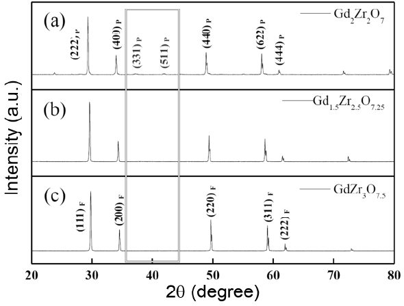
Fig. 2
Raman spectra of Gd2−xZr2+xO7+0.5x ceramics after sintering at 1600°C for 4 h. 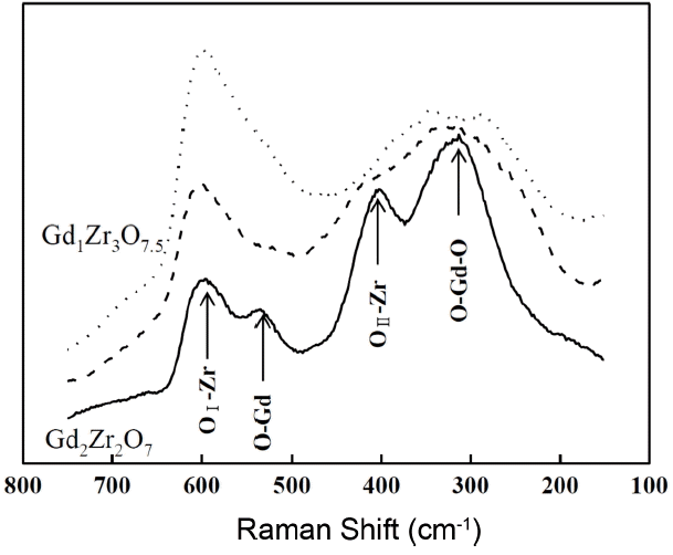
Fig. 3
XRD lattice parameters of Gd2−xZr2+xO7+0.5x ceramics after sintering at 1600°C for 4 h. (* is calculated as a fluorite cell.) 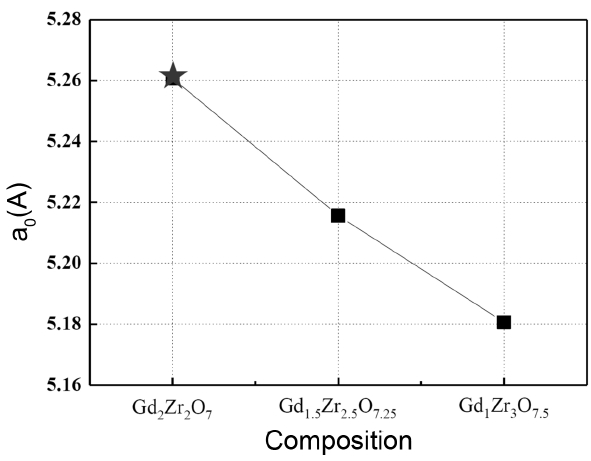
Fig. 4
SEM micrographs from polished cross-sections of Gd2−xZr2+xO7+0.5x after sintering at 1600°C for 4 h, where x is (a) 0.0, (b) 0.5, and (c) 1.0. 
Fig. 5
X-ray diffraction patterns of Gd2−xZr2+xO7+0.5x coatings fabricated by SPS, where x is (a) 0.0, (b) 0.5, and (c) 1.0. 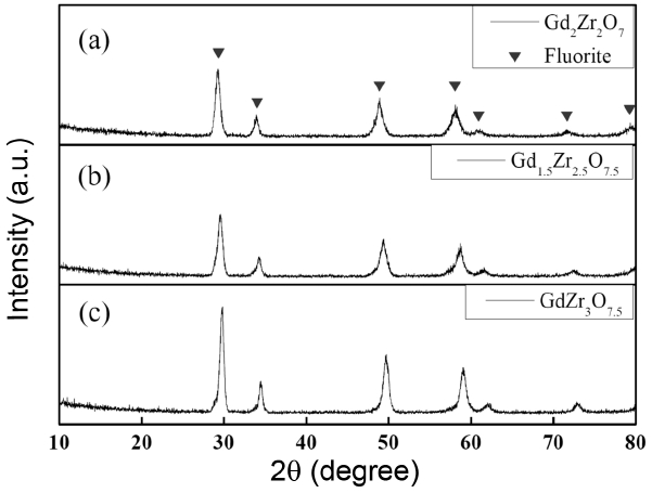
Fig. 6
Raman spectra of Gd2−xZr2+xO7+0.5x coatings fabricated by SPS. 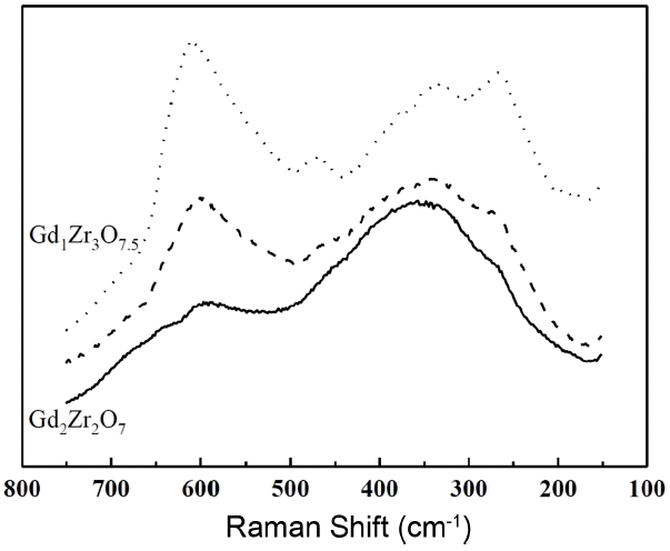
Fig. 7
Surface and cross-sectional SEM micrographs of Gd2−xZr2+xO7+0.5x coatings fabricated by SPS, where x is (a) 0.0, (b) 0.5, and (c) 1.0. 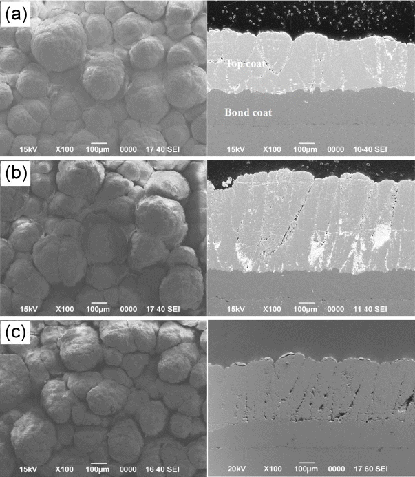
Fig. 8
Thermal diffusivity values of bulk and coating specimens in the Gd2−xZr2+xO7+0.5xsystem, where GZ-0, GZ-1, or GZ-2 is Gd2Zr2O7, Gd1.5Zr2.5O7.25, orGd1Zr3O7.5, respectively. 
Table 1
Compositions of Gd2−xZr2+xO7+0.5x Ceramics Used in This Study
|
# |
ID |
Mole ratio between GdO1.5 and ZrO2
|
Nominal composition calculated for a fluorite unit cell*
|
|
0 (ref) |
GZ-0 |
2.0 : 2.0 |
Gd2Zr2O7*
|
|
1 |
GZ-1 |
1.5 : 2.5 |
Gd1.5Zr2.5O7.25
|
|
2 |
GZ-2 |
1.0 : 3.0 |
Gd1Zr3O7.5
|
Table 2
Apparent Density Values of Gd2−xZr2+xO7+0.5x Ceramics after Sintered at 1600°C for 4 h
|
ID |
Nominal composition calculated for a fluorite unit cell*
|
Nominal molar weight (g/mole) |
Nominal molar volume (cm3) |
XRD density (g/cm3) |
Apparent density (g/cm3) |
Relative density (%) |
|
GZ-0 |
Gd2Zr2O7*
|
608.9 |
1.46 × 10⁻²²
|
6.94 |
6.82 |
98.2 |
|
GZ-1 |
Gd1.5Zr2.5O7.25
|
579.9 |
1.42 × 10⁻²²
|
6.79 |
6.85 |
100.0 |
|
GZ-2 |
Gd1Zr3O7.5
|
550.9 |
1.39 × 10⁻²²
|
6.58 |
6.48 |
98.5 |
REFERENCES
1. DR. Clarke, and SR. Phillpot, “Thermal Barrier Coating Materials,” Mater Today, 8 [6] 22-9 (2005).  2. R. Vaßen, MO. Jarligo, T. Steinke, DE. Mack, and D. Stöver, “Overview on Advanced Thermal Barrier Coatings,” Surf Coat Technol, 205 [4] 938-42 (2010).  3. DR. Clarke, M. Oechsner, and NP. Padture, “Thermal-Barrier Coatings for More Efficient Gas-Turbine Engines,” MRS Bull, 37 [10] 891-98 (2012).  4. C. Kim, YS. Heo, TW. Kim, and KS. Lee, “Fabrication and Characterization of Zirconia Thermal Barrier Coatings by Spray Drying and Atmospheric Plasma Spraying (in Korean),” J Korean Ceram Soc, 50 [5] 326-32 (2013).  5. R. Vassen, X. Cao, F. Tietz, D. Basu, and D. Stöver, “Zirconates as New Materials for Thermal Barrier Coatings,” J Am Ceram Soc, 83 [8] 2023-28 (2000).  6. J. Wu, X. Wei, NP. Padture, PG. Klemens, M. Gell, E. García, P. Miranzo, and MI. Osendi, “Low-Thermal-Conductivity Rare-Earth Zirconates for Potential Thermal-Barrier-Coating Applications,” J Am Ceram Soc, 85 [12] 3031-35 (2002).  7. W. Pan, SR. Phillpot, C. Wan, A. Chernatynskiy, and Z. Qu, “Low Thermal Conductivity Oxides,” MRS Bull, 37 [10] 917-22 (2012).  8. XQ. Cao, R. Vassen, and D. Stoever, “Ceramic Materials for Thermal Barrier Coatings,” J Eur Ceram Soc, 24 [1] 1-10 (2004).  9. JW. Fergus, “Zirconia and Pyrochlore Oxides for Thermal Barrier Coatings in Gas Turbine Engines,” Metall Mater Trans E, 1 [2] 118-31 (2014).  10. H. Lehmann, D. Pitzer, G. Pracht, R. Vassen, and D. Stöver, “Thermal Conductivity and Thermal Expansion Coefficients of the Lanthanum Rare-Earth-Element Zirconate System,” J Am Ceram Soc, 86 [8] 1338-44 (2003).  11. K-H. Kwak, B-C. Shim, S-M. Lee, Y-S. Oh, H-T. Kim, B-K. Jang, and S. Kim, “Formation and Thermal Properties of Fluorite-Pyrochlore Composite Structure in La2 (ZrXCe1− X)2O7 Oxide System,” Mater Lett, 65 [19] 2937-40 (2011).  12. J. Wu, NP. Padture, PG. Klemens, M. Gell, E. García, P. Miranzo, and MI. Osendi, “Thermal Conductivity of Ceramics in the ZrO2-GdO1.5 System,” J Mater Res, 17 [12] 3193-200 (2002).  13. CG. Levi, “Emerging Materials and Processes for Thermal Barrier Systems,” Curr Opin Solid State Mater Sci, 8 [1] 77-91 (2004).  14. S-J. Kim, W-J. Lee, C-S. Kwon, S-M. Lee, Y-S. Oh, H-T. Kim, D-S. Im, and S. Kim, “Phase Formation and Thermo-Physical Properties of GdO1.5-ZrO2 System for Thermal Barrier Coating Application (in Korean),” J Korean Ceram Soc, 51 [6] 554-59 (2014).  15. U. Schulz, B. Saruhan, K. Fritscher, and C. Leyens, “Review on Advanced Eb-Pvd Ceramic Topcoats for Tbc Applications,” Int J Appl Ceram Technol, 1 [4] 302-15 (2004).  16. R. Vaßen, H. Kaßner, A. Stuke, F. Hauler, D. Hathiramani, and D. Stöver, “Advanced Thermal Spray Technologies for Applications in Energy Systems,” Surf Coat Technol, 202 [18] 4432-37 (2008).  17. S. Sampath, U. Schulz, MO. Jarligo, and S. Kuroda, “Processing Science of Advanced Thermal-Barrier Systems,” MRS Bulletin, 37 [10] 903-10 (2012).  18. W. Fan, and Y. Bai, “Review of Suspension and Solution Precursor Plasma Sprayed Thermal Barrier Coatings,” Ceram Int, 42 14299-312 (2016).  19. JB. Nelson, and DP. Riley, “An Experimental Investigation of Extrapolation Methods in the Derivation of Accurate Unit-Cell Dimensions of Crystals,” Proc Phys Soc, 57 [3] 160(1945).  20. D. Michel, and R. Collongues, “Study by Raman Spectroscopy of Order-Disorder Phenomena Occurring in Some Binary Oxides with Fluorite-Related Structures,” J Raman Spectro, 5 [2] 163-80 (1976).  21. R. Leckie, S. Krämer, M. Rühle, and C. Levi, “Thermochemical Compatibility between Alumina and ZrO2-GdO3/2 Thermal Barrier Coatings,” Acta Mater, 53 [11] 3281-92 (2005).  22. R. Shannon, “Revised Effective Ionic Radii and Systematic Studies of Interatomic Distances in Halides and Chalcogenides,” Acta Crystallogr, Sect A: Cryst Phys, Diffr, Theor Gen Crystallogr, 32 [5] 751-67 (1976).   23. K. VanEvery, MJM. Krane, RW. Trice, H. Wang, W. Porter, M. Besser, D. Sordelet, J. Ilavsky, and J. Almer, “Column Formation in Suspension Plasma-Sprayed Coatings and Resultant Thermal Properties,” J Therm Spray Technol, 20 [4] 817-28 (2011).  24. C-S. Kwon, S-M. Lee, Y-S. Oh, H-T. Kim, B-K. Jang, and S. Kim, “Preparation of Suspension in La2O3-Gd2O3-ZrO2 System Via Planetary Mill and Characteristics of (La1−XGdX)2Zr2O7 Coatings Fabricated Via Suspension Plasma Spray (in Korean),” J Kor Powd Metall Inst, 20 [6] 453-59 (2013).  25. WJ. Lee, YS. Oh, SM. Lee, HT. Kim, D-S. Lim, and S. Kim, “Fabrication and Characterization of 7.5 wt.% Y2O3-ZrO2 Thermal Barrier Coatings Deposited by Suspension Plasma Spray (in Korean),” J Korean Ceram Soc, 51 [6] 598-604 (2014).  26. C-S. Kwon, S-M. Lee, Y-S. Oh, H-T. Kim, B-K. Jang, and S. Kim, “Structure and Thermal Conductivity of Thermal Barrier Coatings in Lanthanum/Gadolinium Zirconate System Fabricated Via Suspension Plasma Spray (in Korean),” J Kor Inst Surf Eng, 47 [6] 316-22 (2014).  27. N. Curry, Z. Tang, N. Markocsan, and P. Nylen, “Influence of Bond Coat Surface Roughness on the Structure of Axial Suspension Plasma Spray Thermal Barrier Coatings - Thermal and Lifetime Performance,” Surf Coat Technol, 268 15-23 (2015).  28. C. Kittel, and P. McEuen, Introduction to Solid State Physics; 8th ed. pp. 125-8 Wiley, New York, USA, 1986.
|
|


