1. Introduction
Thermal barrier coating (TBC) for turbine components using ceramic materials with enhanced high-temperature durability is applied to turbine blade, nozzle, etc. as a key component in gas turbines for power generation or turbine engines for aviation. TBC is the technology where the surfaces of Ni-based super-alloy materials are coated with ceramic materials such as yttria (Y2O3) stabilized zirconia (ZrO2) having a low thermal conductivity to protect the metal substrate against hot gas stream. Recently, the research activities about the development of new coating materials with a low thermal conductivity and of the coating technologies to secure the stable structures at high temperature operation condition have been performed so as to improve energy efficiencies by raising the operating temperatures for gas turbine engines.1-4)
In the case of Atmospheric Plasma Spray (APS) widely known as a TBC manufacturing technique, granulated raw powder is melted by plasma flames, and a coating structure is formed with splats in a stacked form on to the substrate. At this time, degradation in thermal shock resistance occurs at high temperatures due to the interlayer pores formed together with the coating layer, unmelted particles, secondary phase particles, etc., which can be associated with the degradation in operation durability at high temperatures. 3,4) Therefore, diversified studies to improve high-temperature durability are being conducted on TBC’s manufactured by the plasma spray method, and particularly, studies on optimization of coating structures are being continuously conducted since the high-temperature durability is closely associated with the latter. Primarily, the studies to obtain optimized coating structures through control of powder conditions such as particle size, shape, structure, etc. of the raw material powder itself and of spray process conditions are being performed, 5-13) as well as the studies on the structure control technology to manufacture TBC’s with coating structures such as segmented microstructure known to have a high compliance to thermal fatigue environments due to excellent strain compliance.14-19) The segmented microstructure is well known to have excellent strain compliance to substrates so as to be advantageous to thermal shock or high-temperature durability.14,16,17)
In the present study, commercial yttria-stabilized zirconia (8 wt% Y2O3 stabilized ZrO2, to be referred to as 8YSZ hereafter) powder was granulated by spray drying method, and TBC was prepared by plasma spray method. In the case of raw material powder, shape and size of the granulated powder was controlled by varying dispersion and heat treatment conditions in the granulation process, and formation behavior of dense and/or porous coating structures was investigated by using the granulated powder prepared. Also, in the case of dense coating, manufacturing conditions for segmented TBC structure through formation of vertical cracks inside the coating were secured by controlling the post heat treatment conditions using plasma flame produced with Ar gas.
2. Experimental Procedure
2.1. Production of granulated powder by using spray dry
By mixing two types of raw materials, i.e. zirconia (ZrO2, particle diameter (D50): 0.3 μm, purity: 99.5%, Zhonglong Hightech Limited, China) powder and yttria (Y2O3, particle diameter (D50): 5 μm, purity: 99.999%, Feilong International Group Co., ltd, China) powder and using a spray dry method, granulated powder of 8wt% yttria stabilized zirconia (8YSZ) for atmospheric plasma spray was prepared. At first, granules were prepared by the spray dry method after undergoing the primary and the secondary mixing processes using a ball mill. The spray dryer employed was domestically-produced DIE FCNM-026R (Dong Jin Spray Drying Technology) model. At this time, upon the secondary mixing process, shape of granules was controlled by varying feeding conditions for the binder (PVA, Polyvinyl alcohol) and the flocculant (NaOH). Also, among the process conditions for spray drying, the inlet temperature was maintained at about 180°C, and the outlet temperature at about 70 ~ 80°C, and the process conditions for size control of granules were secured by varying disc(atomizer) speed from 6000 to 12,000 rpm. To grant strength and to control the extent of densification for as-received granulated powders with different particle sizes and shapes, classification was made after heat treatment in air atmosphere at 1400°C/4 h and 1600°C/4 h, respectively. In Fig. 1, detailed contents of granule preparation process are schematically shown.
2.2. Coating preparation by using plasma spray method
As a comparison item with the prepared granules, reference coating samples were prepared by using commercial YSZ powder (204B-XCL, Sulzer Metco) and atmospheric plasma spray method. Prior to preparation of the coating samples, bond coating was formed by HVOF (High Velocity Oxyfuel deposition, JP5000, PRAXAIR, USA) method to increase adhesion to the 8YSZ top coating. For formation of appropriate bond coating, the substrate surfaces were subjected to blasting treatment under the pressure of 7 kg/cm2 using alumina particles (Fused Al2O3, #46) and an inhalation-type sand blaster so as to increase adhesion between the substrate and the bond coating. As a material for bond coating, a commercial alloy material of Ni-Co-Cr-Al-Y composition (Amdry 386-2, particle diameter: 5 ~ 63 μm, Ni23-Co20Cr12.5Al0.5Y) was used. Thickness of the bond coating was controlled to be about 200 μm.
Substrates used for coating were made of commercial Ni-based super-alloy (Inconel 718), which was fabricated to the size of Φ25.4 and 3 mm in thickness to be used in the form of coupon. For the manufacturing process conditions of top coating with the use of atmospheric plasma spray, the spray distance (gun distance) was fixed at 75 mm, and the gun current and voltage were set as 470 A and 90 V, respectively, with the gun speed maintained at about 1,000 mm/s. Here, the mixing ratio for Ar:He gases was set to be 45/5 NLPM by volumetric ratio, and the powder feeding rate was maintained at 30 g/min. Detailed conditions for the top coating process are shown in Table 1. As the coating apparatus used for such atmospheric plasma spray, Triplex pro™ 200 product of Oerlikon Metco Company (Switzerland) was employed. Process flow chart for the entire manufacturing of bond coating and top coating is shown in Fig. 2. Also, for forming experiments of the segmented structures, coating surfaces were heat treated using Ar plasma flame for the dense coating sample formed with granules of a small particle size among the as-received top coating samples. Here, the change tendency for coating structures was investigated under the plasma processing conditions where the applied current and the number of spray passes were fixed at 470A and 5 times, respectively, with variations of the gun speed in 100 ~ 300 mm/s and of the gun distance in 75 ~ 125 mm.
2.3. Characteristics
By using a particle size analyzer (Beckman Coulter LS Particle Size Analyzer, LS 13 320), particle size analysis was conducted for the granulated powders prepared. For phase analysis of the granules prepared by spray drying and the coating specimens produced by atmospheric plasma spray method, the samples were analyzed by measuring diffraction peaks using an X-ray diffractometer (X-ray diffraction, Rigaku SmartLab, Rigaku, JAPAN) in the range of 2θ = 5 ~ 80° under the conditions of 40 kV, 200 mA and Cu-Kα radiation at the scanning speed of 2°/min. Also, for the granule powders and the coating samples, microstructures were observed using FESEM (Field Emission Scanning electron microscope, Jeol 7100F, JEOL, Japan) under the acceleration voltage conditions of 10 and 5 kV, respectively. In the case of coating samples, samples for observation of cross sections were produced by mounting in epoxy, drying for more than 12 h, polishing of side face to 100 μm with the use of diamond suspension, followed by cleaning in acetone for 20 minutes and drying in a dryer under the temperature condition higher than 80°C for more than 12 h.
3. Results and Discussion
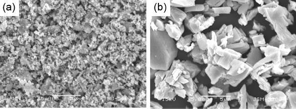
In the present study, 8wt% yttria-stabilized zirconia granules of diversified shapes and sizes were prepared by varying spray dry processes with the use of commercial zirconia powder and yttria powder. In Fig. 3, microstructures of the raw material powders of zirconia and yttria employed in the experiments are shown. In the case of zirconia powder shown in Fig. 3(a), the size of the secondary flocculated phase shows a distribution of about 1 ~ 3 μm while the size of the primary particles is shown to be smaller than 1 μm. In the case of yttria powder shown in Fig. 3(b), secondary particles with an average particle diameter on the level of about 5 μm are observed, while particles as large as 10 μm are also observed.
Observation results by SEM for the shapes of 8YSZ granules prepared by the spray dry method are shown in Fig. 4. For all particles, relatively smooth particle shapes were observed. Size distribution results for individual granule particles measured by the particle size analyzer were cross checked by microstructures through SEM observation. In Fig. 4(a), particles with donut-type shape are observed, and are analyzed to have a size distribution of about 45 ~ 125 μm according to the particle size analysis results. The particles shown in Fig. 4(b) have typical spherical-type shape, and the particle size results could be affirmed to have a distribution of about 45 ~ 125 μm which was similar to the donut-shaped particles of Fig. 4(a). Also, in Figs. 4(c) and 4(d), a structure with relatively smaller size of spherical particles is observed in comparison with the two previous cases. In the case of particles in Fig. 4(c), a particle size distribution of about 15 ~ 90 μm was observed according to the particle size analysis, and a particle size distribution of about 10 ~ 63 μm was exhibited in the case of Fig. 4(d). Concerning the causes for such results, an analysis was conducted in relation to the spray drying process conditions of Table 2. In the case of preparation at a high spray speed by increasing the disc (atomizer) speed, a tendency to form granules having relatively smaller particle sizes was exhibited. Also, the size of the granules formed under the condition of high viscosity of slurry was found to be larger than that when slurry of relatively lower viscosity was used. For the spray conditions related to granule shapes, the tendency to form spherical particles was observed when the slurries in flocculated state was spray dried by using NaOH as a flocculant. On the contrary, when slurry in the highly dispersed state was used without using the flocculant, the tendency to form donut-shaped granules was noted due to surface densification of splat upon spray drying.
Phase-forming behavior of coating samples formed from the granules prepared was analyzed by XRD patterns in Fig. 5. Representatively, coatings formed from two types of granules with different particle sizes were selected together with a coating prepared from a commercial spray powder product as comparison data for the comparative analysis. For all granule powders observed in the range of 2θ = 5 ~ 80°, similar diffraction patterns could be observed. Tetragonal phase was found as a main phase, and weak traces of some cubic phase and monoclinic phase were detected. Based on such results, process conditions for formation of granules with mutually different sizes can be expected to have almost no effects on the phase-forming behavior.
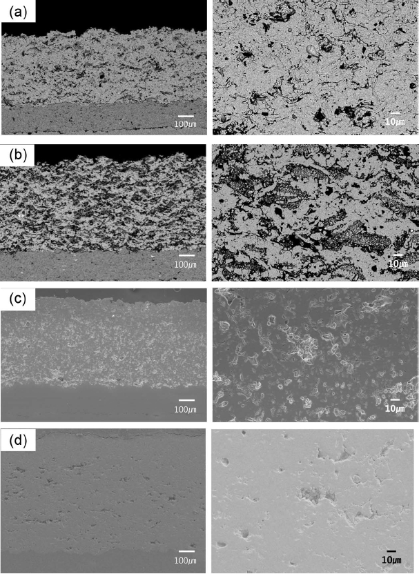
Microstructures of the prepared coating layer were analyzed by SEM as shown in Fig. 6. For the structural analysis in finer regions, the observation results at a low magnification (left side) and a high magnification (right side) are shown for each analysis figure. Coating thickness for all coating samples prepared can be seen to be on the levels of about 200 μm in the case of bond coating, and about 600 μm in the case of top coating. The microstructure of Fig. 6(a) represents the appearance of a cross section for the sample coated by using donut-shaped granules of a coarse size where formation of splat stacking structure is observed, and interconnected pores are also observed in some regions along with formation of pores among splats. Cross sectional structure of the costing samples prepared by using spherical-shaped coarse granules similar to that of donut-shaped granules is shown in Fig. 6(b). Although the size distributions of the granules used are similar with donut-shaped granules, more pores among splats and more regions appearing to be unmelted are observed in comparison with the donut type. It is reported that such results can generally be originated from the difference in specific surface areas between the donut type and the spherical type.8) Namely, upon melting of granules by plasma, donut-shaped granules are believed to be capable of forming a denser structure with a relative increase in the surface area exposed to plasma. Shown in Figs. 6(c) and 6(d) are cross sections of the coatings prepared by using spherical granules of relatively smaller sizes compared with those of Figs. 6(a) and 6(b), and formation of relatively denser structures is noted as compared with the case where coarse granules were used as shown. In the case of Figs. 6(c) and 6(d) using granules of small sizes, a relatively denser structure can also be seen in the case of Fig. 6(d) than in the case of Fig. 6(c).
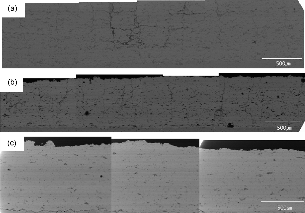
Although such dense structures can increase chemical stabilities against erosion, oxidation, etc. caused by high-temperature fuel gas of outside when used as a thermal barrier coating material, resistance to relatively periodic thermal and mechanical shocks can rather be lowered in comparison with the structures with a high porosity. Hence, preparation of a segmented structure where deformation resistance under periodic thermal, mechanical stresses in planar direction could be increased in the coating was adopted by inducing vertical-type cracking. For this purpose, vertical-type cracks were formed by selecting dense coating shown in Fig. 6(d), and inducing thermal shock on the surface with plasma irradiation onto the coating surface with no powders. Here, forming conditions for more uniform vertical cracks was intended to be secured by controlling moving speed of the plasma gun and distance from the coated substrate. First, the distance between the plasma gun and the coating substrate was fixed at 50 mm with variation in the moving speed of the plasma gun, and the cross sectional microstructures of as-received coatings are shown in Fig. 7. Under the conditions where the distance from the plasma gun to the substrate is rather short at 50 mm, no vertical cracks occurred under thermal shock even when the moving speed of the plasma gun was varied, and it could be seen that the more densification phenomenon due to melting occurred from the surface in the depth direction of coating layer, as the moving speed of the plasma flame is slower. In Fig. 8, formation behavior of vertical cracks was observed by varying the distance between the plasma gun and the substrate at fixed gun speed, 500 mm/sec. In Fig. 8(a) for the case of processing under the conditions where the distance to the substrate was relatively shorter among 3 different types of plasma processing conditions shown in Fig. 8, formation of horizontal cracks together with vertical cracks was found. Also, no formation of vertical cracks was observed when the distance between the coating face and the plasma gun was largest as in the case of Fig. 8(c). By comparison, the case where the vertical cracks occurred appropriately as shown in Fig. 8(b) is considered to the optimum condition in the present experiment for the distance between the plasma gun and the coating substrate. Such difference in formation of vertical cracks dependent on the distance between the plasma flame and the coating face is presumably attributable to the extent of thermal shock is varied as a function of differences in the extent to which the thermal energy due to plasma contact with the surface, and the extent of thermal shock caused by contact and non-contact sections of plasma flame is believed to contribute to the crack formation inside the coating.
4. Conclusions
8YSZ granules were prepared by spray drying method, and size, shape of the granules were affirmed to vary with differences in the process variables for preparation of granules. Also, by utilizing as-received individual granules, coatings were prepared by atmospheric plasma spray method for consideration of the effects of granule conditions on the coating structures. In the case of donut-type granules, relatively denser structures were formed in comparison with the spherical granules, which was presumably due to a difference in the specific surface areas of splat in contact with the substrate. When dense coatings were formed, to form a structure with high thermal and mechanical stress resistance, plasma treated on the coating surface as a post-treatment to form vertical-type cracks in the coating structure. It could be affirmed that the formation extent of the cracks formed inside the coating was exhibited differently as a function of differences in thermal shock condition experienced by the coating surface. In the present study, formation of vertical cracks was affirmed when the distance between plasma flame and coating was about 100mm, and the gun speed about 500 mm/sec.


