


1. Introduction
Porous ceramics are of technological interest because of their potential use in applications. The air permeability, mechanical and thermal properties of this porous material can be controlled according to the changes of porosity and pore size. Porous ceramics have low density and large specific surface area so these are used in various fields due to the pore characteristics that dense materials haven’t.1-5) Among porous ceramics, porous alumina is sintered under an air atmosphere so it is less expensive and easy to obtain its raw material. Porous alumina also has high mechanical, physical, chemical and thermal stability and excellent corrosion resistance and electrical insulating properties, therefore porous alumina can be used widely in the industry. Because of such advantages, the demand for porous alumina is increasing in the display field as well as the semi-conductor field as the subsidiary parts for semi-conductor manufacturing device. However, due to a high volume resistance of approximately 1 × 10¹⁵ Ω·cm of alumina, it is being used limitedly in handling rig, arms, pincette and heater for transferring wafer, vacuum tube parts and spacer for magnetic disc and semi-conductor vacuum chuck that are parts requiring the prevention of static electricity. Among these devices, a vacuum chuck for FPD (flat panel display) is a precision chuck which maintains the glass substrate or semi-conductor wafer.
However, if alumina is used as a vacuum chuck for FPD, a electric charge will be polarized inside the metal layer of thin film due to its high electrical resistance, resulting in a spark discharge and damaging the substrate.6) Therefore, a study on the control of electrical properties of alumina is urgently required in order to solve such electrostatic polarization. To solve such problem metallic oxides are added to alumina and such methods include the method to add both MnO2 and TiO2 to form MnTiO3 or add MnO2 to alumina, forming the second phase with low electrical resistance such as MnAl2O4 and the method to add TiO2 to form excess electron, and it is possible to lower the electrical resistance of alumina through such methods.
Also, excellent air permeability to apply the suction force and high strength to prevent damage from the suction process are required because a vacuum chuck is a device which adsorbs and transfers a substrate using the vacuum suction force. However, porous materials have a low strength generally due to high porosity, so there is a difficulty in using porous materials as a vacuum chuck. To solve this problem, there are several methods to improve the strength of porous alumina. The method to add ZrO2 which is a reinforcing material, the method to increase sintering time and sintering temperature and the method to mix powders in two different sizes are available. Among these methods, the method to mix powders researched by Furnas7) can fill pores between large powders with very fine powders so that high green density can be obtained. Also, the method to mix powders was presented in order to improve low mechanical properties and increase the density of the porous material.8-9) However, if the density of porous material increases, its structure will become more dense due to high density regardless of increased strength so that the permeability will be lowered on the contrary. Therefore, it may be unsuitable to use as a vacuum chuck requiring a high permeability.
In order to solve such problem, it was intended to control the pore structure by generating a large open pore between large powders using relatively large powder mixture in this study, and relative large powders in two different sizes were mixed to obtain a relatively higher density than porous materials produced using powders in the same size and improve the strength. Also, MnO2 and TiO2 were added to control the electrical properties of porous alumina. And changes in the density, mechanical properties and pore structure according to the mixing ratio between powders in two different sizes were examined.
2. Experimental Procedure
The commercial alumina powders in three different sizes were used for the starting raw materials in this experiment, and (S) for small-sized powder, (M) for medium-sized powders and (L) for large-sized powder were named respectively for convenience as shown in Table 1. #600 Mesh (~8.93 μm, 99.51% white aluminum oxide, Kramer Industries, USA) for large-sized alumina powder, #280 Mesh (~33.43 μm, 99.51% white aluminum oxide, Kramer Industries, USA) for medium-sized alumina powders and #180 Mesh (~81.24 μm, 99.35% white aluminum oxide, Kramer Industries, USA) for large-sized alumina powders were used respectively. The same amount of metallic oxides was added to all specimens in order to control the electrical properties of alumina; 2 wt% of TiO2 (99.5% Sigma-Aldrich, USA) and 4 wt% of MnO2 (99% Sigma-Aldrich, USA) were used. The porous material was made only using alumina powders in same size for each specimen. Also, porous material using the mixed powder was made by adding large-sized powders to medium-sized powders at the weight-ratio of 0, 30, 50, 60, 70 and 100 as shown in Table 2. Dry ball milling was carried out for 24 h. PEG (polyethylene glycol, Sigma-Aldrich, USA) was sprayed and mixed as a plasticizer, and then it was die-pressed at a pressure of 25 MPa using the disk-type 36 mm mold. The pressed samples was heated at 600°C to burn out the binder and it was sintered at the maximum temperature of 1600°C with heating rate of 5°C/min for 1 h in an air atmosphere to produce porous material.
In order to check the density variation according to the mixing ratio between powders in two sizes, the weight and volume of specimens produced according to each mixing ratio were measured and the relative density in comparison to the theoretical density was calculated. At this time, the theoretical density was calculated from the composition of raw material powders using the rule of mixture. Also, in order to check the pore size of porous material, it was measured using the mercury porosimeter (AutoPore IV 9500, USA) according to the mercury immersion method. The air permeability was measured using the Capillary Flow Porometer (CFP-1200-AEL, Porous Materials Inc., USA). The shape of powders and the pore structure of porous material were observed using the SEM (JSM-6610, JEOL, Japan), and the 3-point flexural strength was measured using the flexural strength tester (RB302, UNITECH, R&B, Korea) at the span distance of 20 mm after processing the specimens to 3 mm × 4 mm × 30 mm for the strength of porous alumina ceramics. The electrical resistance was measured using the High-Resistance Meter (4339B, Agilent Technologies, USA) after processing the specimens to 20 mm × 20 mm × 2 mm and applying 100 V (+) bias at the temperature of 25°C. In order to check whether a new phase was created due to the reaction between alumina and the added metallic oxides or not and the final phase, the measurement was carried out using the X-ray diffraction (D/MAX 2500 V/PC, Rigaku Corporation, Japan).
3. Results and Discussion
3.1. Air permeability of porous material produced using the powders in the same size
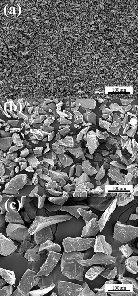
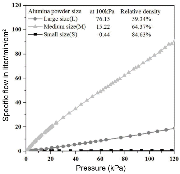
Figure 1 is the microscope images of commercial alumina small-sized powders(S), medium size (M) and large size (L) used in this experiment. Powders have an angled irregular polyhedron shape rather than a circular shape, and it is expected that the filling rate would be low due to powders in angled shape, so it will be helpful for improving the air permeability after sintering. Fig. 2 is the air permeability result of porous material prepared from mixtures with powders in the same size after sintering at 1600°C for 1 h. The porous material produced only using the alumina powders in the largest size (L) among powders in three sizes showed a very high air permeability of 76.15 liter/min/cm2 under the pressure of 100 kPa where the pressure difference between gas flow was approximately 1 atmosphere. The porous material produced only using the alumina medium-sized powders showed 15.22 liter/min/cm2 under the same pressure and the porous material produced only using the alumina powders in the small (S) size showed a very low air permeability of 0.44 liter/min/cm2 under the same pressure.
The reason for such air permeability result can be explained by the difference of the relative density. When comparing the relative density of three kinds of specimens, the relative density of porous material using small-sized powder is 84.63%, showing the lowest air permeability among three kinds of specimens and it is too dense to use it as a vacuum chuck. Also, the porous material from medium-sized powders showed the relative density of 64.37% and the porous material from large-sized powders showed 59.34% which was relatively low, indicating that the porous material had a higher air permeability as the relative density was lower. It is expected that such result is due to a difference in the relative density according to the size of starting powder. It is generally understood that the driving force is to reduce the whole surface energy in system of material, so the powders in a relatively small particle size has a wide specific surface area in case of sintering at the same sintering temperature, and it will have the highest driving force. Also, a vacuum chuck requires a high strength to withstand an impact that could occur when attaching an object for a long period of time. Therefore, the porous material from large-sized powders has a high air permeability, but due to its low relative density, it is expected that it will show a relatively low strength, so there will be a difficulty in using it as a vacuum chuck. The porous material from medium-sized powders also has a low permeability in comparison to the porous material from large-sized powder, so it is considered that it is difficult to use it as a vacuum chuck due to its low vacuum suction force. To solve such problem, it was intended to improve the strength by using increasing the relative density with the powder size mixing method and produce materials with high air permeability using relative large powders of two kinds which can make large open pores between large-sized powders.
3.2. Pore characteristics of porous material according to mixing of alumina powder
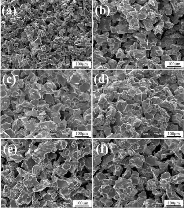
After making green bodies with the mixing ratio shown in Table 2 from medium-sized (M) and large-sized (L) powders, a change in the pore characteristics of porous material sintered at 1600°C for 1 h was observed. Fig. 3 shows the fracture microstructure of porous material using medium-sized powder (a), porous material using powder mixing method (b) ~ (e) and porous material using large-sized powder (f). It can be confirmed that porous material using medium-sized powder (a) consists of relatively fine particles in comparison to porous material using large-sized powder (f) and porous material using large-sized powder (f) has large pores between large-sized powders. Also, porous material using mixing method (b) ~ (e) shows the microstructures of mixture with medium-sized and large-sized powders.
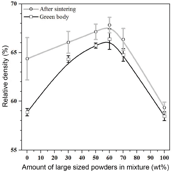
Figure 4 shows the relative density of green bodies and sintered materials according to a change in the content of large-sized powders in medium-sized powder. The green density varies according to the mixing ratio when powders in two sizes are mixed. The green density increased as the content of large-sized powders increased up to 60% and it decreased when the content of large-sized powders exceeded 60%. The density of porous material also changed in the same way with the green density. The sintered density increased as the content of large-sized powders increased up to 60% and it decreased when the content of large-sized powders exceeded 60%. Also, a difference between the green density and the sintered density became larger as the content of medium-sized powders was larger because the medium-sized powders has a larger specific surface area than the large-sized powders so that it has a higher driving force for sintering than the large-sized powder. Among the green density results, green body of M40-L60 showed the highest density value as 66.38%. Among the sintered density results, sintered body of M40-L60 also showed the highest density value as 67.83%.
In order to confirm the effect of large open pores formed by the large-sized powders as the content of large-sized powders in the medium-sized powders increased on a change in the average pore size, the pore structure was analyzed using the mercury porosimetry and the analysis result was shown in Fig. 5. The average pore size of porous material prepared from only medium-sized powders is 9.98 μm, the average pore size of porous material prepared from the mixtures of powders in the medium and large sizes is approximately 16 ~ 19 μm, and the average pore size of porous material prepared from only with large-sized powders is 29.47 μm. It can be expected that the average pore size increases as the content of large-sized powders increases as shown in the result because large pores were generated between powders due to large-sized powders affect the average pore size of the sintered material.
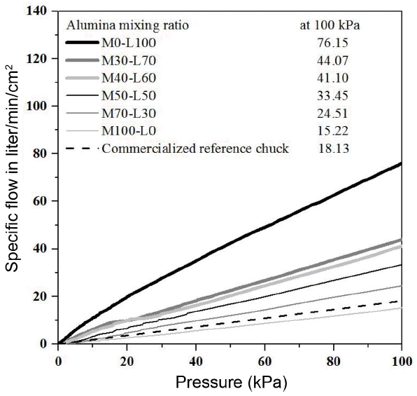
Also, the air permeability was measured in order to check the effect of the content of large-sized powders since the air permeability of porous material was significantly influenced by the pore size. As shown in the average pore size result in Fig. 5, the average pore size increased as the content of the large-sized powders increased, and the air permeability also increased as the content of large-sized powders increased as shown in Fig. 6. Therefore, a change in the average pore size can be confirmed according to the change in the content of large-sized powders and it is expected that the air permeability depends on the average pore size. While the commercialized vacuum chuck as a reference shows a relatively low value of approximately 18 liter/min/cm2 under the pressure of 100 kPa where the pressure difference is approximately 1 atmosphere, the powder mixed material shows high air permeability between approximately 25 and 44 liter/min/cm2 under the same pressure. This shows the level which could be used in parts including air bearing and semi-conductor vacuum chuck that require high air permeability.10)
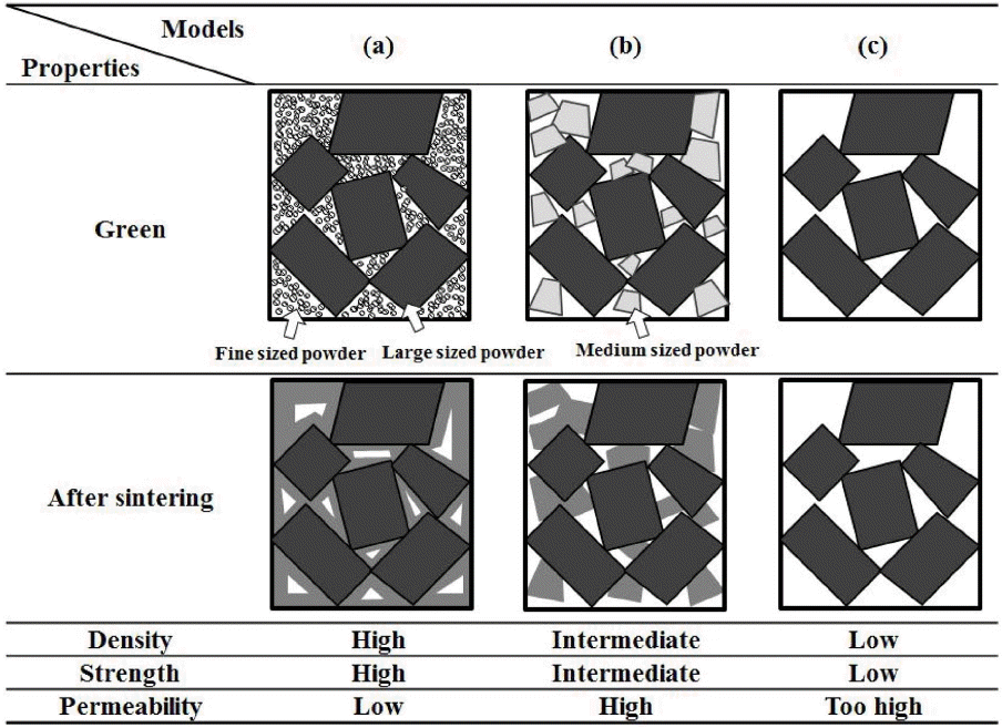
Relatively large powders were used in this study, and a change in the pore structure and mechanical properties according to the mixing ratio between powders in two sizes was examined. Since the pore structure and mechanical properties result from the microstructure, it was expected that the microstructure characteristics of green body and sintered body would vary according the size of starting powders used when powders in two sizes were mixed. In order to find appropriate microstructure for using as a vacuum chuck, microstructures were shown schematically in Fig. 7. Three kinds of microstructures using green body and sintered body in case of mixing powders were compared. Firstly, Fig. 7(a) is the schematic diagrams of anticipated microstructure of green body and sintered body in case of mixing small-sized powders and large-sized powders. Generally, when green body produced by mixing powders in two sizes is sintered, small-sized powders is sintered easily and the spaces of small-sized powders between large-sized powders would be remained as a pore.11) Therefore, it is expected that it will show the highest green density among three kinds of types, so it will have the highest strength after sintering, but due to its high density, it will also have a low air permeability. On the contrary, in case of Fig. 7(c), only large-sized powders is used. Therefore, it is expected that it will show the lowest green density among three kinds of cases, and it is expected that it will show the lowest strength and a relatively high air permeability due to its low density after sintering. Fig. 7(b) shows the anticipated green and sintered body in case of mixing relatively large powders in two different sizes, showing the most similar shape with the result in this experiment. At first, according to the relative density result in this experiment, it has a high green density between 64% and 66%, and the green body only from large-sized powders shows a low green density as approximately 59%. Therefore, interstitial sites between large-sized powders are filled with medium-sized powders when two relatively large-sized powders in two different sizes are mixed and used, so it can be expected that it has a higher filling rate than the case of Fig. 7(c), where only large-sized powders are used. In other words, it is expected that the mechanical properties will be improved after sintering due to a high filling rate. In case of this experiment, powders in two different sizes are relatively large, so unique large pore size of powders is maintained as it is unlike the solid phase sintering behavior at the time of mixing small-sized powders and large-sized powder, so it is expected that it will have a high air permeability. Therefore, it has a high air permeability, and it is expected that it will have a high strength since it has a higher relative density than the porous material produced only with large-sized powder. It is considered that Fig. 7(b) which shows the most similar shape in this experiment would be appropriate to be used as a vacuum chuck.
3.3. Characterization of flexural strength according to powder mixtures
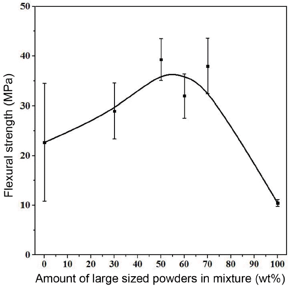
In this study, the powder mixing method was used in order to improve low mechanical strength of porous alumina due to high porosity. Fig. 8 shows a change in the flexural strength according to the mixing rate, the content of large-sized powders (L) in the medium-sized (M) powders. It is confirmed that as the content of large-sized powders increases, the flexural strength increases until the content of large-sized powders reaches 60%, and when the content of large-sized powders exceeds 60%, the flexural strength decreases. When comparing it with the relative density shown in Fig. 4, as the content of large-sized powders increases, it increases until the content of large-sized powders reaches 60%, and when the content of large-sized powders exceeds 60%, it decreases again, and the flexural strength increases as the relative density increases. The flexural strength increased because the filling rate increased as interstitial sites between large-sized powders were filled with medium-sized powders and it had a relatively high relative density accordingly after sintering, so the strength was improved. Also, the spaces between large-sized powders are filled with medium-sized powders, increasing contact points between powders due to a relatively wide specific surface area of medium-sized powder, so the powders become relatively dense due to proper necking formation.
The studies on the density varying according to mixture of starting powders were mainly carried out by German12) and McGeary.13) And the mixing method of Furnas indicating that theoretically it has the highest green density at the volume fraction of the large-sized powders near 60~80 wt% is similar to the relative density result in this experiment. However, above-mentioned German and McGeary were able to increase the relative density through the mixing of different sized starting powders, but the purpose of this experiment is to keep the porosity through large pores created using relatively large alumina, not to produce dense material close to the theoretical density by inducing a high filling rate through mixing, so it is important to increase the air permeability of porous material through this method. Therefore, it was possible to improve the mechanical characteristics by adjusting the mixing ratio of powders and it was also possible to increase the air permeability of porous material by controlling the pore size using large pores of large-sized powders in this experiment.
3.4. Characterization of electrical resistance according to alumina powder mixtures
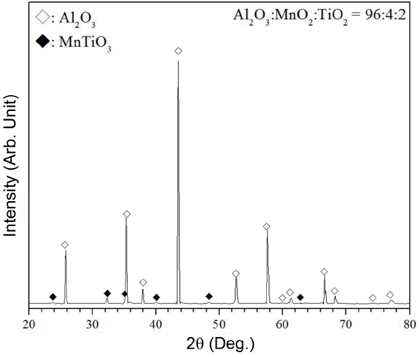
This study focuses on the study on the semi-conducting porous alumina material which has a lower electrical resistance than the conventional alumina. The generally known electrical resistance (volume resistance) of high-purity alumina has a value ranged between 1.7 ~ 7.2 × 10¹⁴ Ω·cm. It is known that the electrical resistance of alumina is influenced by additives and the electrical resistance of alumina with high content of impurities is lower than that of high-purity alumina.14) Therefore, it was intended to lower the electrical resistance of alumina in this experiment by including metallic oxides such as MnO2 and TiO2 to alumina. At first, phase transformation occurs in MnO2 into various phases including Mn2O3, Mn3O4 and MnO according to the temperature and oxygen partial pressure. Therefore, XRD was measured and the result was shown in Fig. 9 in order to confirm the final phase that could be formed by additives. According to the phase diagram of Al2O3-TiO2-MnO reported by Moreira and Segadaes,15) the composition in this experiment is in the area of composition where Al2O3, MnTiO3 and MnAl2O4 coexist thermodynamically. However, in case of composition in this experiment, Al2O3 and MnTiO3 were confirmed mainly as the final phase according to the XRD result. It was caused by that the alumina powders used in this experiment were larger in comparison to MnO2 and TiO2 powders added as additives, so there were less contact points where chemical reaction could occur due to relatively less specific surface area, so less alumina compound formed. Therefore, when large alumina powders was used, a very low peak intensity of MnAl2O4 which could be generated through the reaction with MnO2 was shown, and it is expected that a relative high peak from MnTiO3 which was the compound of MnO2 and TiO2 could be confirmed from the XRD result. Also, the result showing that the peak of corundum which was the high temperature phase of alumina was shifted was shown and it is inferred that metallic oxides make solid solution partially, and it has been reported that TiO2 is soluble to alumina by 0.27% at a temperature ranged between 1300 ~1700°C.16) It has been also reported that such metallic oxides could reduce the electrical resistance of alumina, and as a typical example, when metallic oxides such as TiO2 are added, Al+3 is replaced by Ti+4 according to the non-stoichiometric equation mechanism, creating excess electron and reducing electrical resistance. 17-19) Therefore, the electrical resistance of alumina deceases as the content of TiO2 increases.
Also, 4 wt% of MnO2 was added to all specimens equally, and MnO2 is an additive for alumina material used in LCD photo process and it is known that it can reduce the reflectivity effectively in the photo process due to back color of MnO2,20) and when it is sintered with alumina together, MnAl2O4 is formed.21) It is reported that MnAl2O4 formed in this way has a significantly lower electrical resistance as approximately 1.0 × 10³ Ω·cm in comparison to alumina and,22) MnTiO3 has a electrical resistance of approximately 1.8 × 10⁷ Ω·cm.23) It is considered in this study that low electrical resistance of alumina was mainly influenced by MnTiO3.
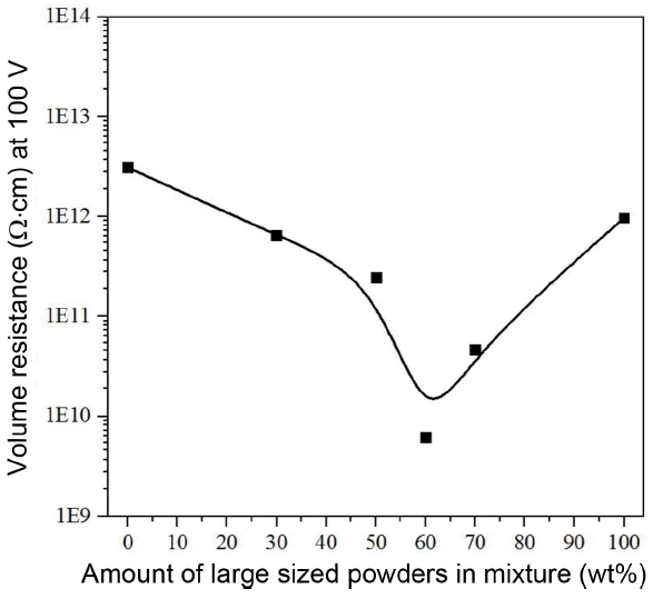
Figure 10 is the graph for confirming a change in the electrical resistance of porous alumina according to the mixing powders in two different sizes, and it was confirmed whether the electrical resistance changed or not as the content of large-sized powders in the medium-sized powders increased. The electrical resistance result of all specimens shows a significant lower value in the range between 2.4 × 10¹¹ and 6.2 × 10⁹ Ω·cm in comparison to approximately 1 × 10¹⁵ Ω·cm which is the generally known electrical resistance of alumina. It is inferred that the electrical resistance of alumina decreased due to the addition of metallic oxides, so it is expected that the problem of electrostatic polarization which could occur in the FPD process due to a high electrical resistance of alumina mentioned above could be solved. Also, when comparing the relative density of porous alumina shown in Fig. 4 with the electrical resistance in Fig. 10, the electrical resistance was directly opposite to the relative density result. It is confirmed that as the content of large-sized powders increases, the electrical resistance decreases rapidly until the content of large-sized powders reaches 60%, and the relative density decreases and the electrical resistance increases until the content of large-sized powders reaches 100% after exceeding 60%. It is inferred from such result that a relationship between the electrical resistance and the relative density exists. The interstitial sites between large-sized powders are filled with the medium-sized powders as the relative density becomes higher, so the filling rate increases and the distance between powders becomes closer, ensuring proper necking formation, so it becomes more easier for excess electron created from the substitution of metallic oxides to move in alumina porous material. Also, it is confirmed that it has a lower electrical resistance than the pure alumina due to the second phase which has a low electric resistance including MnAl2O4 formed by alumina and MnO2 and MnTiO3 formed by MnO2 and TiO2.
4. Conclusions
It was possible to improve the mechanical strength of porous alumina by increasing the relative density using the method to mix powders in two different sizes and increasing the air permeability through the generation of large open pores using relatively large powders. A possibility to produce porous alumina having a low electrical resistance by adding metallic oxides to alumina was confirmed. In case of porous alumina prepared from the above process, the flexural strength increased and the electrical resistance decreased as the relative density increased. Among them, M50-L50 material showed an excellent flexural strength of 43.5 MPa and M40-L60 material showed a relatively high density of 68.30% and the lowest electrical resistance of 6.2 × 10⁹ Ω·cm. It was also confirmed that the average pore size of porous material increased as the content of large-sized powders in medium-sized powders increased, and it had an excellent air permeability of approximately 25 ~ 45 liter/min/cm2 under the pressure of 100 kPa where the pressure difference was approximately 1 atmosphere.