1. Introduction
The Monte Carlo (MC) method has been used to simulate the microstructures of materials.1,2) Grain growth in polycrystalline that has no liquid phase was the main subject of the simulations. In these simulations, every cell or lattice point has a unique number that indicates the crystallographic orientation; this number changes randomly depending on the Boltzmann probability, which is a function of energy change. Thus, when there is a rule that two neighboring lattice points which possess identical numbers have lower energy, as in Potts model,1,2) the system comes to have larger and larger agglomerates of lattice points that have identical numbers with increasing simulation time, i.e., Monte Carlo steps (MCS). In this way, MC simulation mimicked the grain growth in polycrystalline. Thereafter, the simulation was used for wider investigations such as grain growth, recrystallization, abnormal grain growth, phase separation, and solidification.
In the late 1990s, Tikare and coworkers3-5) used MC simulation to study coarsening during liquid-phase sintering. They designated liquid particles by giving them a particular number, say 0, and caused temporal evolution only by allowing exchange of numbers (or particles) between neighbor lattice points. The numbers that indicate crystallographic orientations can also change their values only at this exchange. That is, during exchange, a solid particle moves to a neighbor site and changes its crystallographic orientation. In this way, the total numbers of solid and liquid particles in the simulation lattice do not vary as time passes; such a system is called a conserved-order-parameter system. The gathering of identical numbers occurs as before; however, in this case it is achieved not by flipping numbers but by exchanging numbers, which imitates the diffusion of solid atoms through a liquid. Tikare et al.3-5) observed that Ostwald ripening occurred in their simulation via the Gibbs-Thomson effect, which is realized by the solution and reprecipitation of solid particles. They studied the effects of temperature and liquid content on grain growth rate and grain size distribution. 3-6)
Matsubara and coworkers7-9) made similar studies. However, they omitted the steps in which solid particles diffuse into a liquid and, instead, they moved the solid particles to other grains as soon as those particles left the old ones. This method reduced the simulation time and made the solid grains angular, like the grains in sintered ceramics.
One interesting point in Tikare’s work5) is that the particular number that represents a liquid can be interpreted as indicating another phase, for example, a vapor. Therefore, using the same idea, the diffusion of solid particles in a vapor or the diffusion of vapor particles in a solid can be simulated. In fact, Tikare and coworkers10-17) used similar methods to study the densification of powder compacts. To simulate the diffusion of vapor particles, they employed new algorithms such as minimum-energy exchange10) and long-distance exchange.13) Using these methods, they realized the fast diffusion of vapor particles and reproduced the warpage of a sintered body.13,15)
Recently, the phase field method, which had been a powerful tool in the simulation of dendritic growth in molten metals, has been employed to simulate densification during sintering.18-19) In particular, Villanueva et al.19) studied densification during liquid-phase sintering and showed in a simulation that the rearrangement of solid grains during liquid-phase sintering does take place. Because it requires the collective motion of solid particles, this rearrangement process cannot be made to happen in MC simulation.
In this work, we attempted to simulate densification during liquid-phase sintering by using the MC simulation that was designed by Tikare et al.3-5) Although it cannot simulate the rearrangement of solid grains, the algorithm of MC simulation is so simple that it can be coded and improved easily compared to phase field modeling. In order to simulate densification during liquid-phase sintering, we made a lattice that had all three particles, i.e., solid, liquid, and vapor particles. We studied densification and pore growth as well as grain growth during liquid-phase sintering and discussed the effects of wetting angle and interfacial energy on microstructural evolution.
2. Simulation Method
Microstructure is represented by numbers that can be interpreted as indicating particles at lattice points. In this work, the liquid and vapor particles are given the numbers 0 and 201, respectively, and the solid particles are given one number randomly among 1 to 200. Two neighboring lattice points can exchange their particles according to the Boltzmann probability, depending on the energy change produced by that exchange. The energy is given as follows.
Seven kinds of bond energies are given depending on the phases of the neighboring particles: solid-solid with the identical numbers (Ess), solid-solid with different numbers, i.e., grain boundary (Egb), solid-liquid (Esl), solid-vapor (Evs), liquid-liquid (Ell), liquid-vapor (Elv), and vapor-vapor (Evv). In this work, these energies are given as Ess=−1.5, Egb=−0.4, Esl=−0.8, Evs=0, Ell=−0.8, Elv=0, and Evv=0. The bonds between solids with identical numbers are strongest, while the bonds between solids with different numbers are weaker than the bonds between solids and liquids. This indicates that the grain boundary can be replaced (wetted) by liquids.
The exchange is executed when a random number between 0 and 1 is smaller than the Boltzmann probability, given as follows.
A square lattice of size of 300 × 300 was used for the two-dimensional (2D) simulation and a cube lattice of 100 × 100 × 100 was used for the three-dimensional (3D) one. Simulations were run for up to 500,000 Monte Carlo Steps (MCS) for 2D and 250,000 MCS for 3D. Temperature (kT) was fixed at 0.25 for the former and at 0.35 for the latter. Periodic boundary conditions were used for both. The grain sizes were measured based on a cluster counting algorithm developed by Leath20); microstructures were visualized graphically using the VTK graphic library.21)
Densification was represented by using the special initial arrangement of particles. At the beginning, numbers were given to lattice points while maintaining the relative numbers of solid, liquid, and vapor particles at 7: 2: 1. The five-layer-thick outer region of the lattice was set as a vapor region, which mimics the specimen surface in experiments. Densification was represented by the movement of vapor particles from the inner region to this outer region of the vapor phase.
3. Results and Discussion
3.1 Coarsening and densification in a 2D lattice
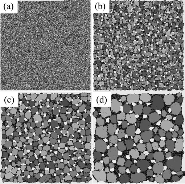
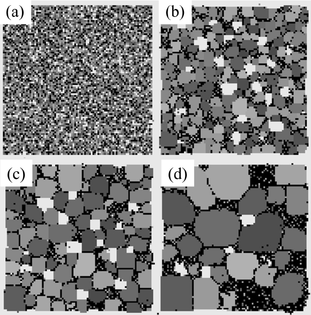
The typical evolution of microstructures obtained from the MC simulation is shown in Fig. 1. The vapor regions of five-layer thickness are located near outer boundaries although these white regions are too thin to be distinguished in the figures. Particles of solids, liquids, and vapors tend to gather with increasing time. This is referring to as coarsening or grain growth. These terms can be applied not only to solids but also to liquids and vapors.
Solid grains disperse in a liquid because they have degenerate numbers and high grain-boundary energy between different numbers. In contrast, liquid and vapor phases have only one number and so they are expected to have a long and connected morphology, as that of a percolating cluster. In fact, the liquid phases that are colored black in Fig. 1(d) are connected, as expected, but the vapor phases colored white are dispersed as solid grains. It is believed that the vapor phases are trapped inside the liquids because the solid-liquid bond is much stronger than the solid-vapor bond. These isolated vapor phases experience a coarsening process through the solution and reprecipitation of vapor particles in the same way as solid grains do.
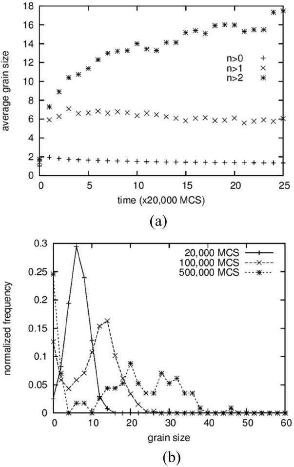
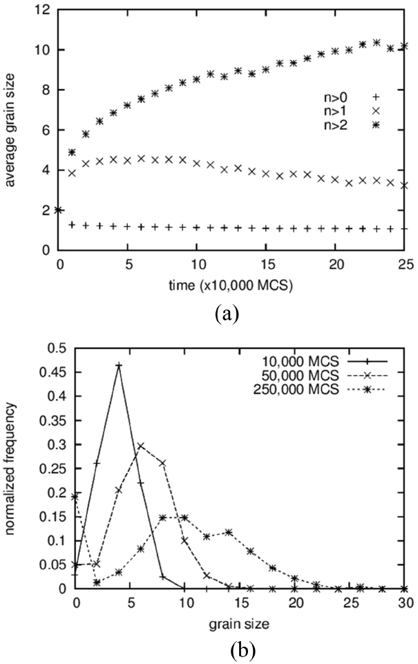
The average grain size and the grain size distribution are shown in Fig. 2. Three different data points are shown in Fig. 2(a). From the bottom are shown the average values of all solid grains, the average except for grains composed of only one particle, and the average except for grains composed of only one and two particles. The lower two curves exhibit slightly decreasing patterns with increasing time after sudden increase at the beginning. Because a decrease in average size cannot occur in the coarsening process, this means that the grains composed of one or two particles cannot be regarded as “grains.” That is, these small clusters are either diffusing particles or unstable embryos that formed by accidental collisions of two particles. This result is in contrast to those of Tikare et al.,5) in which only one-particle clusters are excluded from averaging. The origin of this difference is not clear yet but, in any case, the minimum size of the grains was regarded as three particles in this work.
The average size of the solid grains is below 2 at the start and reaches 18 at 500,000 MCS (Fig. 1(d)). It should be noted that the size of the number 2 indicates a grain composed of 4 particles. Therefore, even if the clusters of 1 and 2 particles are not counted in the averaging, the average size can be smaller than 2 if there are many grains made up of 3 particles. The grain size distributions form bell-shaped curves, as shown in Fig. 2(b), but it was not possible to compare them quantitatively with the theoretical distributions 3,5) because they show severe scatterings.
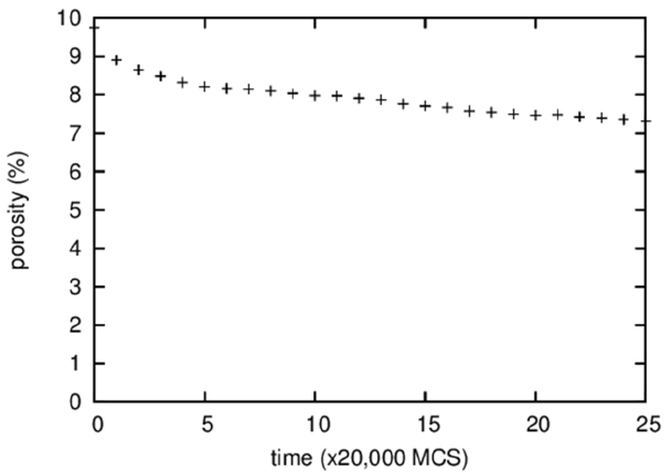
Figure 3 shows the temporal evolution of the fraction of vapor particles that are isolated in a solid or a liquid, i.e., the porosity. It is difficult to discern visually any change in the porosity of the microstructures shown in Fig. 1; however, quantitative measurement revealed a decrease in porosity from 10 to 7% during 500,000 MCS. This decrease in porosity, in other words, densification, is believed to result from the Gibbs-Thomson effect that predicts transport of vapor particles from pores of large curvatures inside a specimen to a specimen surface of small curvature. The densification rate depends on the solubility and the diffusivity of vapor particles in a liquid or a solid.
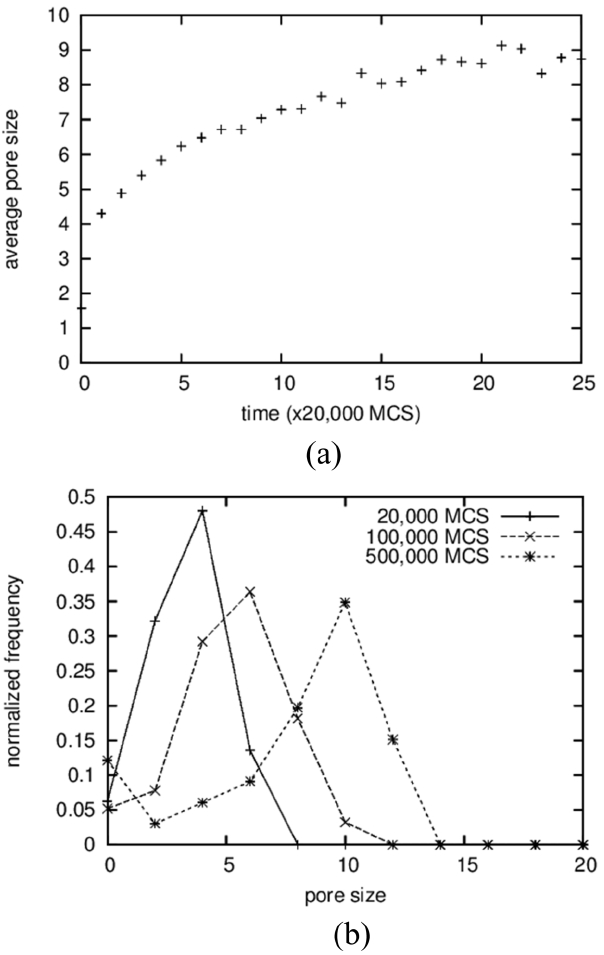
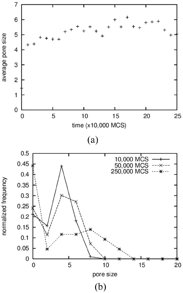
The average sizes and the size distributions of pores are shown in Fig. 4(a) and 4(b), respectively. In the case of pores, clusters made up of 2 particles were counted in the averaging operation; the results show a monotonically increasing curve (Fig. 4(a)), in contrast to the case of solid grains. The size distributions were also obtained, including for the vapor-particle pairs; even the results in the 3D simulations in the next section used the same cutoff. The average pore size increases from below 2 to around 9. The increase in the average size of the pores is the result of a coarsening process identical to that of solid grains. On the other hand, the average sizes of the pores are approximated as half of those of the solid grains, as can be seen in Fig. 2(a), and this ratio can be found directly in the microstructures shown in Fig. 1. The reason why pores are smaller than solid grains is not clear. It is suggested that solid particles dissolve more readily because they have higher degeneracy, which means a higher entropic contribution. And, a high concentration in a liquid results in fast grain growth.
3.2 Effect of wetting angle on microstructure in 2D MC simulation
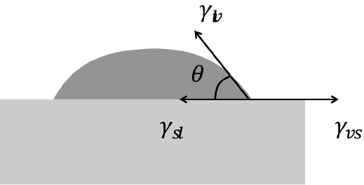
Tikare and coworkers1-3) reported realistic MC microstructures showing solid grains dispersed in a liquid matrix. They gave two and a half times higher energy to the grain boundary than that of the solid-liquid interface. If the microstructure is composed of three phases including vapor particles, it can be expected that the structure will become more complex and that the details will depend critically on the wetting angle. The wetting angle is determined by a force balance of three interfacial energies, as shown in Fig. 5. The interfacial energies shown here are different from the bond energies (Esl, Elv, Evs) described in the simulation-method section. The bond energies are interpreted based on an atomistic viewpoint and are given in such a way that bonds between solids are strongest (largest in negative value), and any bond with a vapor has zero strength. On the other hand, the interfacial energies shown in Fig. 5 are the excess energies that are needed to form interfaces from bulk phases. Here, the formation energies, which are spent in forming the bulk phases, are not a matter of concern and can be given values of zero, as in the previous works by Tikare et al.3-5) In their work, because the numbers of solid and liquid particles were fixed during simulation, the formation energies had no effect on the microstructure and it was possible to justify the selection of zero formation energies. The same conclusion can be made in this work, in which the numbers of solid, liquid, and vapor particles are fixed. To make all the bulk formation energies zeros, the interfacial energies need to be calculated again based on the following excess-energy formula:
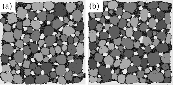
γlv and γvs can be calculated in similar ways, and the bondenergy values can be replaced by the interfacial energy values as follows; Ess= 0, Egb = 1.1, Esl = 0.35, Evs = 0.75, Ell = 0, Elv=0.4, and Evv=0. The results of the MC simulation based on these values are shown in Fig. 6(b). The microstructural features such as the average grain size, grain size distribution, average pore size, and porosity are very similar to those of the previous results (Fig. 6(a)). This comparison indicates that various microstructures of liquid-phase sintered materials can be reproduced by varying only these four interfacial energies.
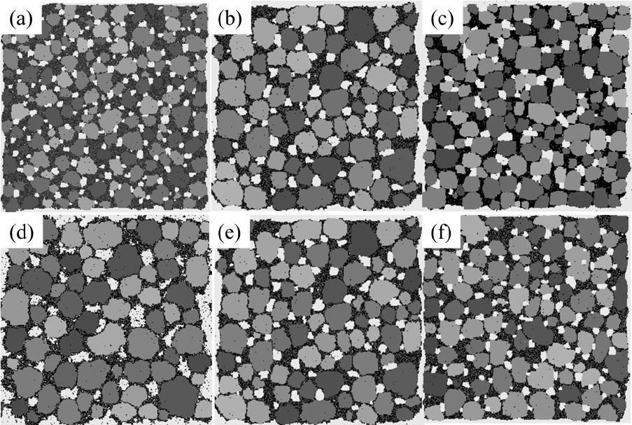
The effects of wetting angle (or interfacial energies) on microstructures were tested by varying the Esl and Elv values in the old value set. Above all, the interfacial energy values in the old value set, used in the simulation shown in Fig. 1, were found to satisfy the relation γvs = γsl + γlv, which means that complete wetting (θ = 0) is achieved. In fact, since the interfacial energy has an entropic term that depends on the temperature, the three interfacial energies would be closer to one another, and the wetting angle would be slightly larger than zero. Keeping this in mind, the solid-liquid interfacial energy was changed first. From left to right in the upper row of Fig. 7, it can be seen that γsl(Esl) increases, and so does a wetting angle. The increase in the solid-vapor interface length confirms that the wetting angle increases in order. Also, the dark liquid phase becomes vivid in order and this shows that the amount of solid particles that dissolved into a liquid is reduced. Interestingly, however, the sizes of the grains and pores do not change in order but exhibit their largest values at the center image. This makes it difficult to make a simple relation between the wetting angle and the growth rate.
Second, the liquid-vapor energy changed. In contrast to the case of γsl(Esl), the liquid-vapor energy underwent a serial change. As can be seen above, from left to right, the wetting angle increases in the lower row in Fig. 7 and grains and pores become smaller in order. The slow growth of pores on the right can be explained by the lower solubility of the vapor particles in liquid. However, the slow growth of solid grains cannot be explained because the solubility of the solids did not change. These two examples show that the bond energies or the interfacial energies are related to various thermodynamic variables, and so they change the microstructures in complicated ways.
3.3 Coarsening and densification in a 3D lattice
The microstructures obtained from the 3D MC simulation are shown in Fig. 8. The obvious difference from the 2D results shown in Fig. 1 is the slow growth of pores and the fast reduction in areal fraction of pores, that is, the fast densification. It should be noted that these two aspects are independent of each other.
In the first place, the growth of pores is analyzed by comparing it to that of solid grains. While the average size of solid grains increased 5 times from 2 to 10, as shown in Fig. 9(a), the pore size fluctuates and stays at around 5 for a long time after a sudden increase at the beginning from 2 to 5 (Fig. 12(a)). The size distributions show rather comparable results in which the peak positions move from 4 to 10 for solid grains (Fig. 9(b)) and from 4 to 8 for pores (Fig. 12(b)). For solid grains, the average sizes are close to the peak positions but, for pores, the average sizes are lower than the peak positions. These two results indicate that the sluggish increase in the average pore size is caused not by the slow growth of large pores but by the increase in the number of small pores composed of 2 to 3 vapor particles. In fact, the value at the size zero in the distribution (Fig. 12(b)) increases with increasing time. The size zero indicates clusters composed of 2 to 3 vapor particles. The reason that the small pores increase with increasing time is simply thought to be that the initial concentration of vapor particles in the liquid was too low, such that more and more vapor particles dissolved into the liquid with increasing time to meet the equilibrium concentration. And, small clusters formed accidently by the collisions of these dissolved vapor particles.
The pores in Fig. 8(d) did not noticeably grow compared to pores in Fig. 8(c) or Fig. 8(b), while the number of pores clearly decreased. This is in contrast to the previous 2D result, in which the sizable pores grew as fast as the solid grains. This can be resolved by considering the 3D pore structures shown in Fig. 10. The dispersed round pores shown in Fig. 10(b) are about two times larger in diameter than the pores shown in Fig. 10(a). Thus, it can be explained that the small pores in Fig. 8(d) were obtained merely by cutting a 3D microstructure with a plane that is far from the centers of the large pores. This shows why careful consideration is needed in analyzing 2D cross-sectioned microstructures.
Next, the porosity change is analyzed. In the 3D microstructures shown in Fig. 10, the number of pores can be seen to decrease dramatically from about 200 to 20. However, because the sizes of pores clearly increased as well, the change in porosity cannot be easily predicted. Quantitative measurement of porosity shown in Fig. 11 reveals a dramatic decrease in porosity. The porosity decreases by more than half, from about 7 to 3%. It should be noted that it was possible to obtain the low initial porosity of 7% because one-particle pores are not counted. The substantial densification in 3D compared to that in 2D (Fig. 3) could be a consequence of the small lattice, in which vapor particles can diffuse out in a short time.
4. Summary
Densification during liquid-phase sintering was simulated using MC simulation. A decrease in porosity and growth of pores and grains were clearly illustrated. The cutoff size in calculation of the average size of solid grains or pores was found to need further discussion. Only four interfacial energies were found to be sufficient to describe the various microstructures; however, it was not easy to predict their exact effects on the growth rate of solid grains and pores. MC simulation is expected to be used more frequently in studies regarding densification in liquid-phase sintering.


