


1. Introduction
The use of personal portable devices is rapidly growing in everyday life, and there is a risk of important personal information being exposed to people nearby through display screens. For example, personal information can be leaked when messages or e-mails are displayed on personal portable devices when they are being used on public transportation. Therefore, attaching information security films to the displays of mobile phones or laptops is becoming increasingly common.1,2)
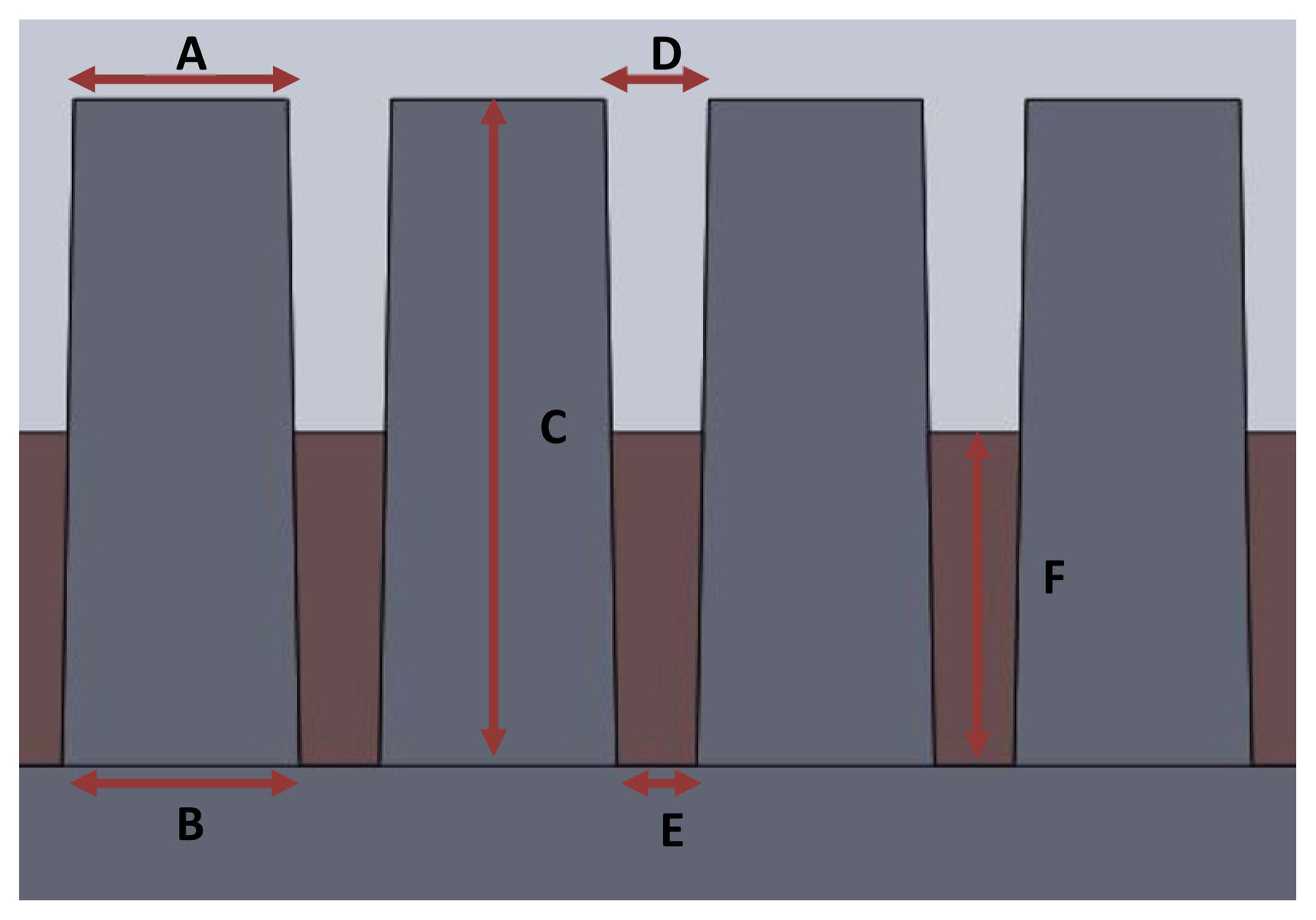
Most information security films use microlouver film technology. In microlouvers, patterns with high aspect ratios are precisely arranged and inter-pattern spaces are filled with shadowing materials in order to decrease the screen viewing angle by allowing for viewing from the front while blocking views from the sides. An important parameter in the fabrication of microlouver films is aspect ratio, which is the ratio of pattern height to width, as it is important for determining film security performance. Existing microlouver films are fabricated by repeatedly bonding several layers of transparent and shadowing films and cutting them vertically. This method, however, makes the films expensive because it involves numerous processes and long production times.3,4) Moreover, common shadowing materials such as black carbon that are used to fill the microlouver pattern and improve its opacity to block side viewing can also significantly decrease optical transmittance from the front.
This study aims to develop a few-step process for fabricating high-quality information security films filled with shadowing materials suitable for microlouver patterns using nanoimprinting and nano-inking.5,6) The following research process was conducted to fabricate microlouver films with excellent security characteristics through a controlled viewing angle. First, film security characteristics were investigated according to shadowing material type for filling an isosceles trapezoidal pattern using an optical simulation method, and the results were verified through experiments. Next, optical simulations were performed to investigate the effects of filling height of the optimized shadowing material in the microlouver pattern. Finally, microlouver pattern films with high-refractive-index shadowing materials were fabricated using nanoimprint patterning and nano-inking, and their optical characteristics were evaluated. The results were also compared with the simulated values.
2. Experimental Procedure
Before conducting experiments, computer simulations were performed using optical simulation software (Optisworks, OPTIS KOREA) to predict film optical characteristics according to filler shadowing material and filling height. The Optisworks software can predict the optical characteristics of a structure modeled through Solidworks (Dassault Systems Korea) by deriving light paths. Table 1 shows the simulation conditions and sizes of the patterns used in this study. Simulation were performed to investigate the distributions of light from the front irradiated from back side after passing through the structure and security characteristics according to shadowing material and nanoink height. The microlouver films used in experiments were fabricated in the following sequence through the silicon stamp mold and nanoimprint process.5,6) A UV-curable resin (ND-938-6, refractive index n = 1.48, NP Chemical, Korea) was applied to a polyethylene terephthalate (PET) film, which was then compressed with a pre-fabricated isosceles trapezoidal silicon mold. A microlouver-patterned film was fabricated by curing the resin with 120 W UV irradiation and removing the mold.6-8) Four oxides with high refractive indices, i.e., ZnO (n = 2.00), ZrO2 (n = 2.15), TiO2 (n = 2.34), and CuO (n = 2.63), were selected as shadowing materials for microlouver filling. The nano-inks (Dittotechnology Co., Korea) had concentrations of 20 wt% and were composed of 10 - 20 nm nanoparticles. The nano-inks mixed with resin were applied onto the cured films using a bar coater.9) After nano-ink filling, the films were dried at room temperature for two hours. To investigate the optical characteristics of the fabricated samples, luminance was measured according to viewing angle using a luminance meter (PR-655, Photo Research Inc., USA) and a fabricated angle mold.9) An electro-luminescent light source with a high diffusivity was used, and the relative luminance was measured using the luminance meter in the angle range of −80° to +80° with respect to the front through the holes in the angle mold. The luminance measured in the system of this study includes the light intensity of various paths by the refraction or reflection in addition to transmission.
The relative luminance ratio (RLR) at 30° with respect to the front was defined as shown in equation (1):
where L(−30°) is the luminance value at −30°, L(+30°) is the luminance value at +30°, and L(front, 0°) is the luminance value at the front.
The surfaces and cross-sectional shapes of the microlouver patterns were observed using a dual interference contrast microscope and a high-precision field emission scanning electron microscope (SEM) (ThermoFisher, Nova Nano SEM 450, USA), respectively. In addition, the optical transmittance in the visible wavelength range was measured using a UV-visible spectrometer (Mega 800, Scinco Co., USA).
3. Results and Discussion
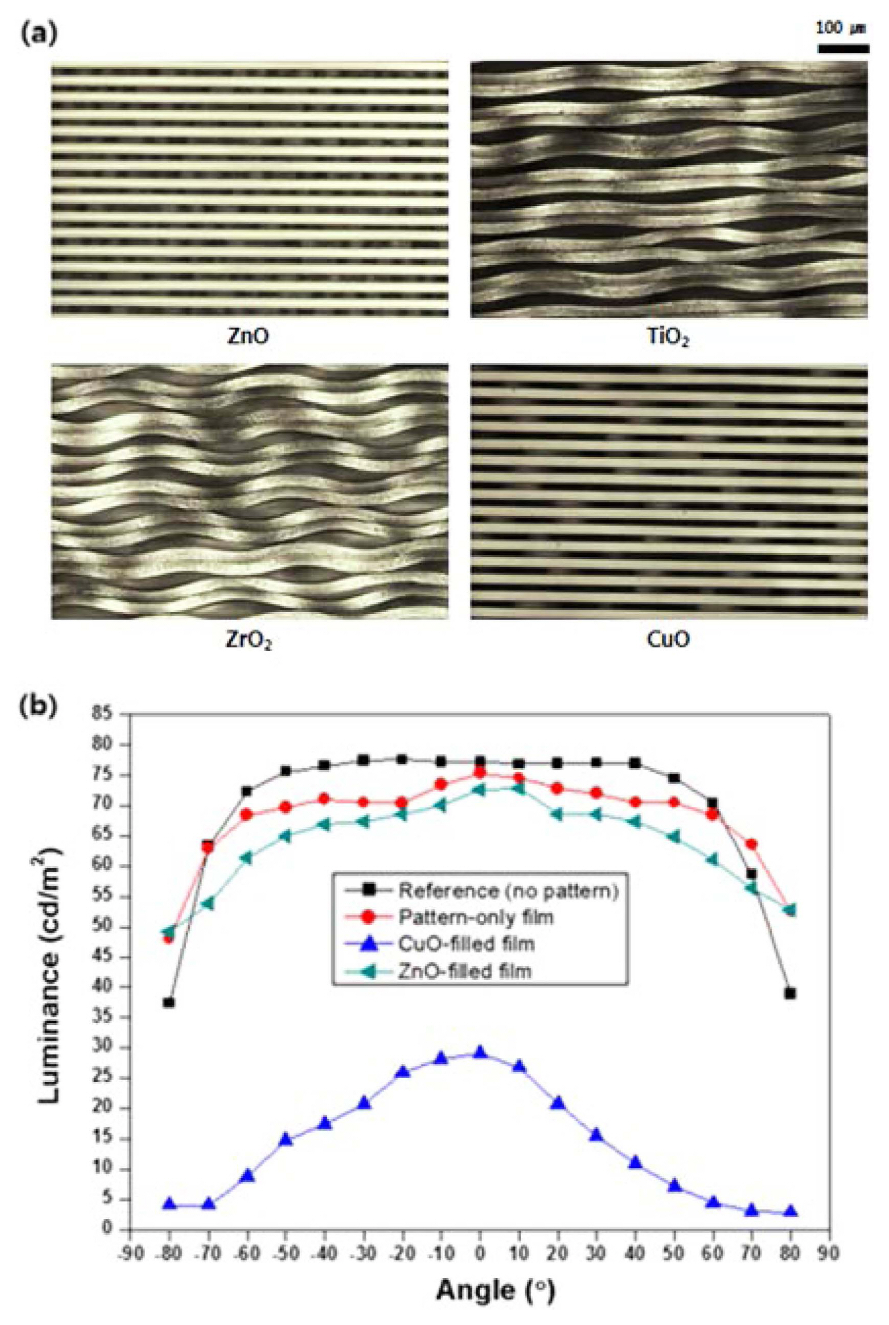
Figure 1(a) shows the light distribution images of the prepared films irradiated from the back side to the front and luminance distribution curves according to the direction predicted by the simulation software. The light distributions of the flat film without a pattern, the film with only an isosceles trapezoidal pattern, and films with various filled shadowing materials were compared. When the light distribution was circular in shape, as in the image of the film without a pattern, a clearly isotropic light distribution occurred according to viewing angle. For the film with a pattern but no filler, the light distribution was deformed compared with an isotropic distribution owing to light interference. When the patterns were filled with shadowing materials with high refractive indices (CuO, TiO2, ZrO2, and ZnO), the light distribution images deviated from circularity, and optical visibility was limited in certain directions. Fig. 1(b) shows the calculated RLRs with respect to the front according to angle, which demonstrate the amount of transmitted light shown in Fig. 1(a). The films filled with shadowing materials exhibited similar RLR reduction tendencies with increasing viewing angle, and no significant differences were present depending on filling material. The RLR values were approximately 0.7 at 45° with respect to the front and 0.6 at 60°.
Figure 2(a) shows planar optical microscope images of fabricated microlouver films with microlouver pattern spaces filled based on the simulation results with nano-inks using the bar coating method. The microlouver patterns were fabricated using nanoimprinting. The patterns were not distorted when ZnO and CuO nano-inks were applied but were distorted after the solvent dried when ZrO2 and TiO2 nanoinks were used. This is likely because ZrO2 and TiO2 had relatively high viscosity values of 4.65 × 10⁻³ Pa·s and 5.04 × 10⁻³ Pa·s, respectively, and thus larger attractive forces caused by surface tension were applied to the resin pattern surfaces during the solvent drying process.10) Fig. 2(b) shows the experimental luminance values according to viewing angle of the PET reference film with no pattern, the film with only a microlouver pattern, and the films filled with CuO and ZnO shading materials. For the films with no pattern and with only a microlouver pattern, RLRs with respect to the front were close to 1 for angles up to 60°, thus showing no information security characteristics. For the films with ZnO and CuO shading materials, however, the luminance significantly decreased for angles up to 60°. In the case of CuO, however, the overall luminance was significantly reduced. This is likely because the CuO nano-ink had a very low optical transmittance; the film with a microlouver pattern filled with CuO looked very dark even to the naked eye. As a result, the ZnO nano-ink, which had a relatively high optical transmittance and did not cause distortion of the microlouver pattern, was selected as a shading material candidate. In addition, to adjust the optical transmittance and information security characteristics of the microlouver film, the optical characteristics of the film were investigated according to ZnO filling height through simulation and experimental measurements.
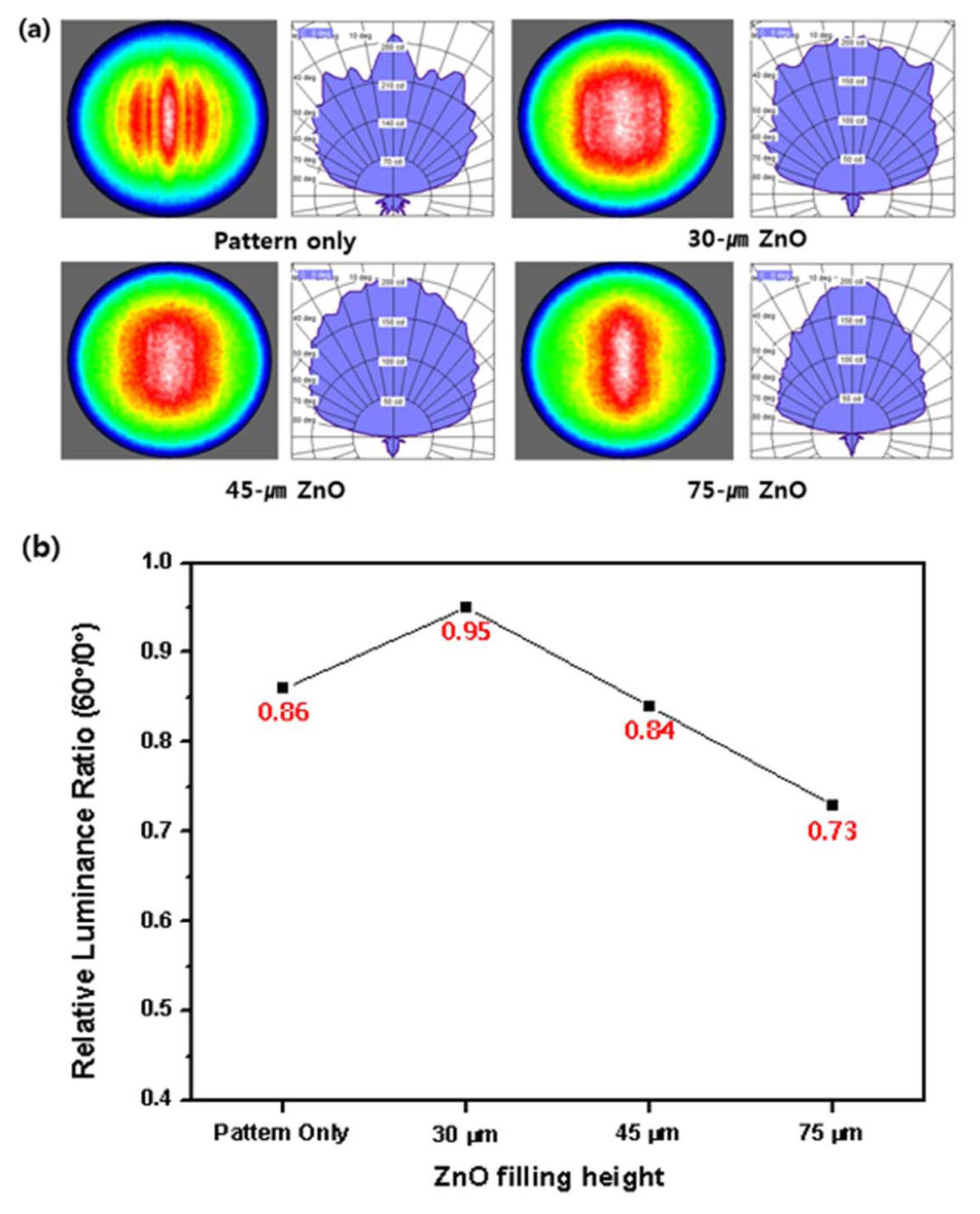
Figure 3(a) shows the simulated light distribution images and luminance distribution curves according to angle for different ZnO filling heights with light irradiation from the back. When there was only a pattern on the film, interference occurred, and the light distribution image exhibited several overlapped ellipses. The luminance distribution curve depending on direction also had periodicity due to interference and exhibited a pointed maple-tree-leaf shape. When ZnO filling was used, the degree of interference decreased, and the light distribution images were not separated. In addition, the protruding parts in the luminance distribution curves significantly decreased. As the ZnO filling height increased, the light distribution images and distribution curves changed from a square-like shape to a circle and finally to a long triangular shape, indicating different optical characteristics depending on the angle. Fig. 3(b) shows the RLRs calculated at 60° according to ZnO filling height for the light sources in Fig. 3(a). For the pattern-only film, the RLR at 60° was 0.86 due to interference effects despite the lack of shading material. The RLR increased to 0.95 for the ZnO filling depth of 30 μm but decreased to 0.73 for the filling depth of 75 μm; the films thus exhibited excellent security characteristics.
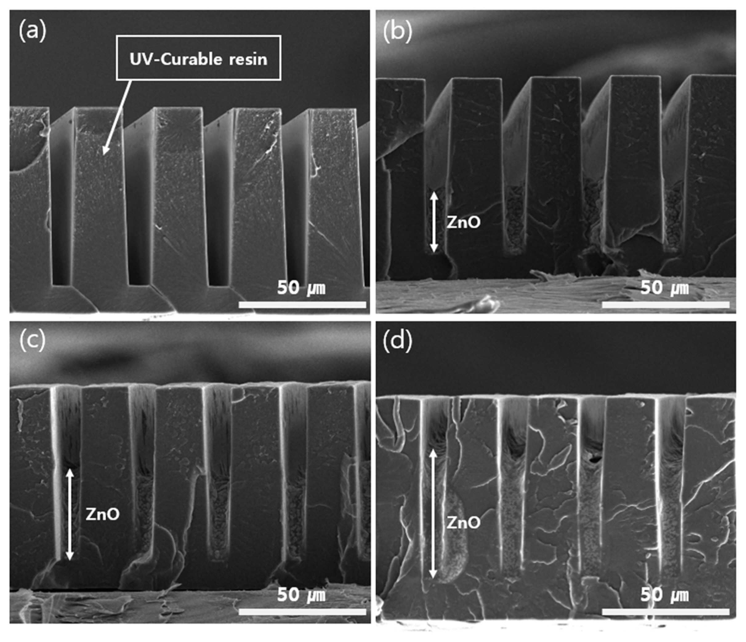
Figure 4 shows the cross-sectional SEM images of the information security films with the fabricated microlouver patterns and various ZnO filling heights. Silicon was processed and used as a stamp mold, and resin was fabricated with an isosceles trapezoidal microlouver pattern with a high aspect ratio using the UV nanoimprint process. The repeated geometry and dimensions of the patterns designed in the simulation were successfully transferred onto the PET films. The ZnO filling height increased depending on the number of bar coating repetitions of the resin with the nano-ink. Even when the ZnO filling process was repeated five times, the side walls of the microlouver patterns were hardly damaged. In the experiment, approximately 15 mm of the ZnO nano-ink was applied per coating. With repeated coatings, the cross-sectional images of the film patterns confirmed that the ZnO filling height increased. However, two, three, and five repetition coatings of ZnO filling exhibited heights of 31.5, 44.5, and 70.1 μm, respectively, with some processing errors.
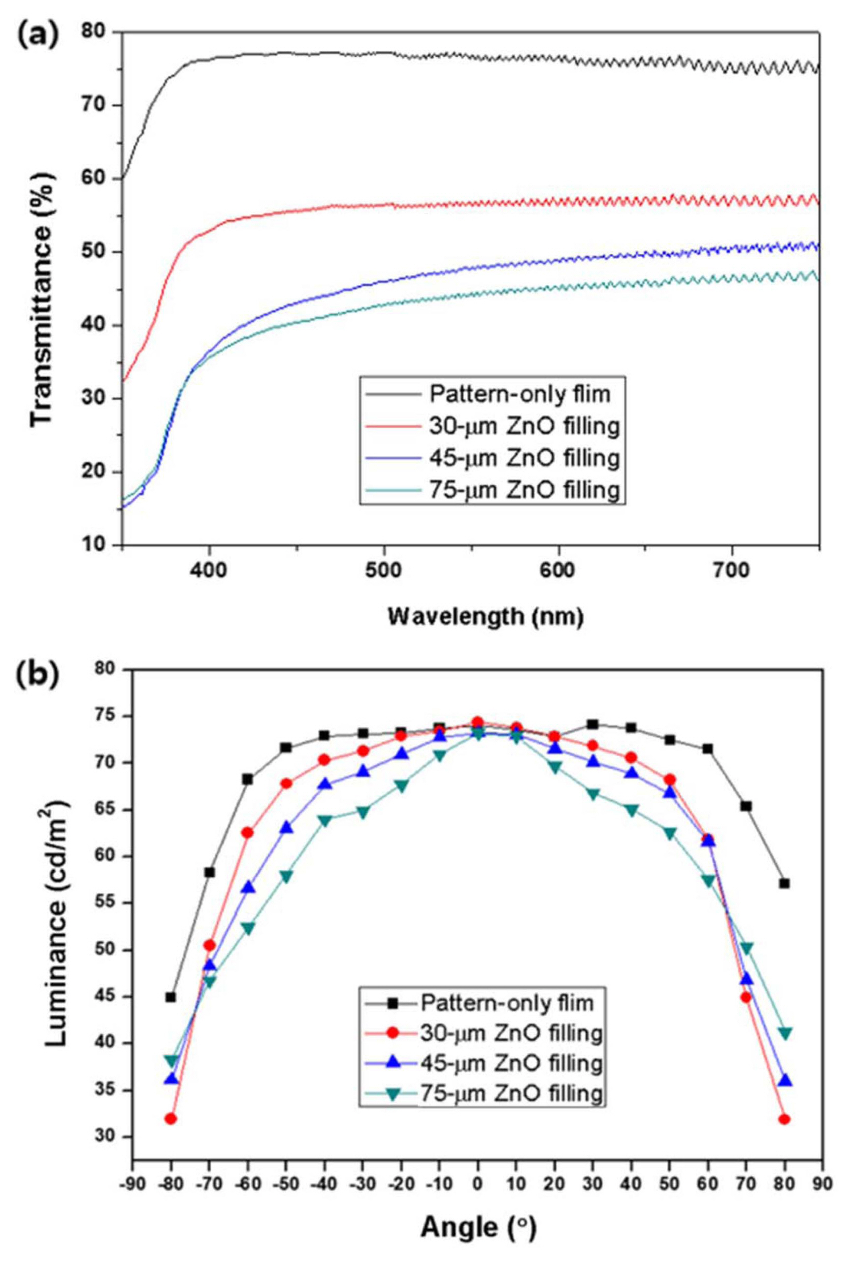
Figure 5(a) shows the measured optical transmittances of the microlouver-patterned films shown in Fig. 4 in the visible wavelength range. The pattern-only film without ZnO filling exhibited a transmittance of 76.8% at a wavelength of 550 nm. As the nano-ink filling was repeated, the transmittance value continuously decreased, reaching 44.4% for the film with a ZnO filling height of 75 μm. Fig. 5(b) shows the variation in luminance of the patterned films according to measurement angle measured by the system devised in this study. For the pattern-only film, the RLR value was close to 1 until the measurement angle reached 50°, indicating that the security effect was not significant. When ZnO was applied, however, the luminance sharply decreased compared to the front as filling height increased.
Table 2 shows the RLR values at 30° and 60° according to ZnO filling height measured in Fig. 5 and optical transmittances measured for a wavelength of 550 nm. A comparison of the experimental RLR values measured at 60° with the simulated values in Fig. 3(b) showed that the results were similar, especially for the films with ZnO filling heights of 45 μm and 75 μm. For the film with a ZnO filling height of 75 μm, the RLR values measured at 30° and 60° were 0.9 and 0.75, respectively, indicating excellent security characteristics.
Figure 6 shows the actual display images with the information security films at various viewing angles. The microlouver films with a ZnO filling height of 75 μm were used. When the films fabricated in this study were placed on an actual display, the display screen was almost perfectly recognizable from both the front and 15° side. However, accurate information acquisition was difficult at 30° side due to significant darkness and no information was recognizable at 60° due to severe display blackening.
4. Conclusions
Information security films capable of protecting personal information by reducing the viewing angle for a display screen were designed using optical simulation software. It was confirmed that the film structure, with high-refractive-index shadowing materials applied to a certain height in the spaces between the high-aspect-ratio isosceles trapezoidal microlouver patterns, showed excellent information security characteristics. Information security films were fabricated based on the simulation results by applying the high-aspect-ratio isosceles trapezoidal pattern to a photosensitive PET resin film using a silicon mold in a UV nanoimprint process. For the shadowing material, ZnO, which did not distort the microlouver pattern geometry in the nano-inking process and exhibited a relatively high optical transmittance, was determined as the most appropriate material. For the information security film with a ZnO filling height of 75 μm, the RLRs measured at 30° and 60° with respect to the front were 0.90 and 0.75, respectively, indicating the film’s excellent information security characteristics. The proposed method of fabricating microlouver pattern films using UV nanoimprinting and ZnO nano-ink filling is thus deemed to be a promising technology for fabricating information security films that control display viewing angles according to user position in terms of economic efficiency and process convenience.