| Home | E-Submission | Sitemap | Login | Contact Us |  
top_img
J. Korean Ceram. Soc. > Volume 55(1); 2018 > Article
Ji and Kim: Construction and Application of Experimental Formula for Nonlinear Behavior of Ferroelectric Ceramics Switched by Electric Field at Room Temperature during Temperature Rise

Abstract

A poled lead zirconate titanate (PZT) cube specimen that is switched by an electric field at room temperature is subject to temperature increase. Changes in polarization and thermal expansion coefficients are measured during temperature rise. The measured data are analyzed to obtain changes in pyroelectric coefficient and strain during temperature change. Empirical formulae are developed using linear or quadratic curve fitting to the data. The nonlinear behavior of the materials during temperature increase is predicted using the developed formulae. It is shown that the calculation results can be compared successfully with the measured values, which proves the accuracy and reliability of the developed formulae for the nonlinear behavior of the materials during temperature changes.

1. Introduction

Piezoelectric ceramics are widely used in devices and equipment such as ferroelectric memory (FRAM), ultrasonic motors, sonar detectors, and micro electro mechanical systems (MEMS). Research on the application and development of piezoelectric ceramics is also widely pursued. The application of a significant load or electric field to a piezoelectric system can result in excessive concentration of stress or electric fields in the ceramic material due to the complexity of the system or the presence of defects, which causes unexpected domain switching and rapid temperature changes. As a result, the internal structure of the ceramic material often changes to produce macroscopic nonlinear behavior and variations in the material properties. Degradation in system performance is observed due to such unexpected domain switching. In order to prevent system instability due to nonlinear behavior, experimental observation and analysis of nonlinear behavior of piezoelectric ceramic materials under various load conditions must be made. A wide range of related studies have been carried out. Zhou and Kamlah,1) Liu and Huber,2) and Kim3) observed and analyzed the nonlinear behavior of the materials when electric field and stress are applied at room temperature. Recently, research on the nonlinear behavior of the materials at room temperature has been extended to high temperatures. Lee and Kim4) and Selten et al.5) measured and analyzed the nonlinear behavior of the materials caused by electric fields at room and high temperatures, while Weber et al.6) measured and analyzed the nonlinear behavior caused by stresses at room and high temperatures. Grunbichler et al.7) used the finite element method to predict and understand the nonlinear behavior of piezoelectric actuators due to stress, electric fields, and temperature changes. Also, to develop an empirical formula for predicting experimental observations of piezoelectric materials, Ji and Kim8,9,10) observed and analyzed the nonlinear behavior of the materials when they are subject to stress and electric fields at room and high temperatures.
In the present work, relatively simple empirical formulae for the experiment results of Ji and Kim11) are presented. Moreover, the presented empirical formulae were used to calculate the polarization and strain responses of piezoelectric materials during temperature increases, and comparisons were made with measurements.

2. Experimental Procedure

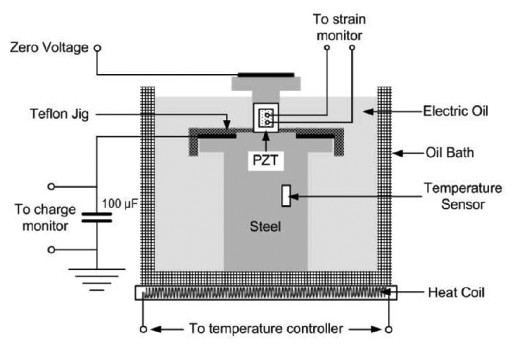
In the present work, the experimental data of Ji and Kim11) were used to present new formulae for the prediction of ferroelectric ceramic behavior at high temperatures. The experimental method of Ji and Kim11) is presented simply here. For ferroelectric specimens, PZT specimens of regular hexahedron shape with 10 mm sides were used. The followings are the properties of the specimen material, provided by the manufacturer (PZT5H1, Morgan Technical Ceramics, UK): the Curie point is 200°C, coupling factor kp = 0.60, piezoelectric coefficients d31 = −250 × 10−12 mV−1 and d33 = 620 × 10−12 mV−1, elastic compliance coefficients s33 = 21.9 × 10⁻¹² m2N−1 and s11 = 17.7 × 10⁻¹² m2N−1. Here, the subscript 3 refers to the polarization direction; the subscript 1 refers to the transverse polarization direction. Initially, the specimen is poled in the negative direction and a total of 14 electric fields of different magnitude were applied at the reference temperature of 20°C. The range of reference remnant polarization P3R0 induced by an electric field was from −0.26 to +0.26 Cm−2. After poling, the leakage current density was measured over 5,000 s and the specimen was stabilized, then followed by temperature increases to 110°C at a rate of 1.2°Cmin−1 along with the invar specimen (Product No. 318-0285-3, Danyang, China). During temperature increases, remnant polarization P3R and thermal outputs ɛG/R and ɛG/S of the invar and ceramic specimens were measured. Here, the thermal output changes refer to the variations of strain gage outputs value during temperature rises. Then, thermal expansion coefficients in the longitudinal and transverse directions α3 and α1 of the ceramic specimen were calculated using the thermal expansion coefficient of the invar specimen αR.12) Polarization was measured indirectly using the Sawyer-Tower circuit; a Keithley 6514 was used to measure the voltage of the capacitor serially connected to the specimen. Temperature was controlled by placing the specimen in an oil bath (2408 PID controller, EUROTHERM, UK), shown in Fig. 1, filled with an insulating oil (MICTRANS Class1-No2, MICHANG OIL IND. CO., Pusan, Korea), and using a heat coil installed on the bottom of the oil bath. All data were collected at a sampling rate of 100 Hz and the data were processed using the LABVIEW program through a DAQ board (PCI 6221, National Instruments, TX, USA).

3. Results and Discussion

3.1. Pyroelectric Coefficient and Strain Calculations During Temperature Increases

Electric fields of various magnitudes were applied in the direction opposite to the polarization of PZT specimens, causing poling in the negative longitudinal direction at reference temperature 20°C. Switching is induced by the applied electric field and an internal state of specific reference remnant polarization is obtained. Then, the electric field was removed, and temperature is increased to 110°C. During temperature increases, remnant polarization P3R and thermal expansion coefficients in the longitudinal and transverse directions α3 and α1 were measured. Fig. 2(a) shows measured remnant polarization P3R, and Figs. 2(b) and (c) thermal expansion coefficients in the longitudinal and transverse directions α3 and α1 during temperature increases. Only five states of reference remnant polarization P3R0 are plotted in Fig. 2(a) out of the total 14 remnant polarization states. In Fig. 2(a), it was observed that when P3R0 was negative, the value of P3R increased, on the other hand, when P3R0 was positive, P3R decreased, with increase in temperature. Additionally, it was observed that P3R is almost constant when P3R0 is near zero. As in Fig. 2(a), only five states of longitudinal and transverse remnant strains are plotted in Figs. 2(b) and 2(c) out of fourteen, longitudinal thermal expansion coefficients in the former plot and transverse in the latter. Thermal expansion coefficients of ferroelectric specimens were calculated using the thermal expansion coefficients of the invar specimen, as demonstrated in Ji and Kim.11) In Figs. 2(b), longitudinal thermal expansion coefficient tends to decrease with increase in temperature, while in Fig. 2(c), transverse thermal expansion coefficient increases and then remain constant. Measured remnant polarization and thermal expansion coefficients are then used to calculate pyroelectric coefficients and strains. First, by estimating the rates of changes in remnant polarizations with temperature, pyroelectric coefficient p3 is obtained. The values of pyroelectric coefficients, calculated for the temperature range between 20°C to 110°C, for five chosen reference remnant polarization states, are shown as symbols in Fig. 3(a). In the figure, pyroelectric coefficients are plotted with respect to temperature for five constant values of reference remnant polarization P3R0. The plotted symbols of p3 fit well with straight line, given by Equation (1) below:
(1)
p3=aPθ+bP,
where, aP refers to the slope of the fitting straight line and bP refers to the intercept of the line at zero temperature. The values of aP and bP are plotted verse P3R0 for the whole range of reference remnant polarization between −0.256 Cm−2 and +0.263 Cm−2 in Fig. 3(b). In the figure, aP is shown to fit with a straight line and bP with a parabolic curve, both expressed as
(2)
a^P(P3R0)=aP1P3R0+aP0,b^P(P3R0)=bP1(P3R0)2+bP1(P3R0)+bP0,
Substitution of Eq. (2) into Eq. (1) results in Eq. (3).
(3)
p^3(P3R0,θ)=(aP1P3R0+aP0)θ+[bP2(P3R0)2+bP1(P3R0)+bP0].
Using Eq. (3), one can estimate pyroelectric coefficient p3 when reference remnant polarization P3R0 and temperature θ are given.
Now turn to the calculation of longitudinal and transverse strains. Thermal expansion coefficient is the rate of change in strain with respect to temperature. Thus, Eq. (4) below can be used to calculate strains from measured thermal expansion coefficients.
(4)
(S3R)i+1=α3(θi)(θi+1-θi)+(S3R)i,(S1R)i+1=α1(θi)(θi+1-θi)+(S1R)i,
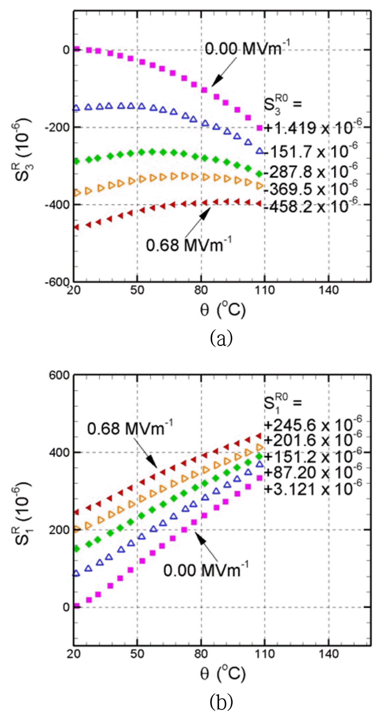
Among fourteen measured states, longitudinal and transverse strains are calculated for five specific states of remnant strains and plotted with temperature in Figs. 4(a) and (b), respectively. In Fig. 4(a), as the magnitude of electric field increases, S3R0 changes from zero to negative values. When the values of S3R0 are relatively small, longitudinal strain tends to decrease with increase in temperature; on the other hand, when S3R0 is less than −400 × 10−6, it increases with temperature. This can be explained by microscopic process of domain switching. When the magnitude of electric field is small, switching is not sufficient and most domains remain parallel to the longitudinal x3 direction. When electric field is sufficiently large, the ratio of domains with polarizations parallel to the transverse x1 axis increases due to electric field-induced switching, leading to increases in S3R with temperature rise. Fig. 4(b) shows the variations of transverse strain S1R with temperature increase at five chose states of reference remnant transvers strain S3R0. Here, unlike Fig. 4(a), S1R increases with temperature for the five chosen states. The state of maximum S3R0 in Fig. 4(b) corresponds to the state of minimum S3R0 in Fig. 4(a). At the maximum S3R0 state, the magnitude of applied electric field is the largest, which causes the largest switching in the specimen. Most domains arrange in the vertical direction parallel to the x1 axis, thus resulting in lower increases in S1R with temperature than other four state in the figure. The cases of S3R0=-458.2×10⁻⁶ in Fig. 4(a) and S1R0=+245.6×10⁻⁶ in Fig. 4(b) correspond to the same state at the reference temperature. It is interesting that longitudinal and transverse strains increase simultaneously as temperature increases at the specific state. In the case of isotropic materials, strains change in the same rate in all directions with temperature increases. The similar increases in longitudinal and transverse strains with temperature in Figs. 4(a) and 4(b) for the specific state, S3R0=-458.2×10⁻⁶ in Fig. 4(a) and S1R0=+245.6×10⁻⁶, suggest that the specimen behaves like an isotropic material after an application of electric field of sufficient magnitude.
Let us apply the equations in Eqs. (1) - (3) to calculate strains. The same procedure is used for both longitudinal and transverse strains, so only the calculation of longitudinal strain will be dealt with here. The variations of longitudinal thermal expansion coefficient α3 with temperature for five chosen states of S3R0 are plotted in Fig. 5(a). It is shown that thermal expansion coefficient data in the figure fit adequately with straight lines, whose equations are given by
(5)
α3=aS3θ+bS3,
where aS3 refers to the slope of fitting straight line and bS3 the intercept of the line at zero the temperature. The distributions of aS3 and bS3 over S3R0 from +1.419 × 10⁻⁶ to −458.2 × 10⁻⁶ are plotted in Fig. 5(b). The data of aS3 and bS3, marked with symbols, fit well with straight lines, expressed as
(6)
a^S3(S3R0)=aS31S3R0+aS30,b^S3(S3R0)=bS31S3R0+bS30,
Substitution of Eq. (6) into Eq. (5) results in Eq. (7) below.
(7)
a^3(S3R0,θ)=(aS31S3R0+aS30)θ+bS31S3R0+bS30.
Using Eq. (7), one can estimate longitudinal thermal expansion coefficient α3 when reference remnant longitudinal strain S3R0 and temperature θ are given. In a similar manner, one can estimate transverse thermal expansion coefficient when S1R0 and θ are given.

3.2 Comparison of the Proposed Formula and Experimental Results

Pyroelectric coefficient p3 is the rate of change in remnant polarization P3R with temperature θ, so it can be expressed as p3=dP3Rdθ. Substitution of this relation into Eq. (1) yields
(8)
dP3Rdθ=a^P(P3R0)θ+b^P(P3R0),
Changes in remnant polarization P3R during temperature increase can be extracted from Eq. (8) for a constant value of P3R0.
(9)
P3R=P3R0+θ0θ(aPθ+bP)dθ,P3R=P3R0+aP2(θ2-θ02)+bP(θ-θ0),
Substituting Eq. (2) into Eq. (9) gives Eq. (10) below, in which the variation of remnant polarization P3R with temperature θ is determined for given values P3R0 and θ0 are given.
(10)
P3R=P3R0+12(aP1P3R0+aP0)(θ2-θ02)+[bP2(P3R0)2+bP1(P3R0)+bP0](θ-θ0).
In this work, reference temperature θ0 is 20°C. The values of all coefficients in Eq. (10) are listed in Table 1. Applying Eq. (10) and Table 1 to the data in Fig. 2(a) gives the prediction results shown in Fig. 6. The symbols in Fig. 6 represent the measured data and the curves represent the calculation results by Eq. (10). Fig. 6(a) shows the plots of changes in remnant polarization P3R with temperature θ and Fig. 6(b) the plots of pyroelectric coefficient p3 with θ. In Fig. 6(a), the measurements and predictions of remnant polarization P3R are in a good agreement with each other. The predictions of pyroelectric coefficient were also found to agree approximately well with measurements.
Experimental formulae for longitudinal and transverse remnant strains S3R and S1R were also developed in a similar manner, just like Eq. (10). The only difference is the linear and quadratic equations in Eqs. (2)2 and (6)2. The values of all coefficients for the strain formulae are found in Table 1. Fig. 7 shows the calculation results for strains. Fig. 7(a) shows the plots for longitudinal remnant strain S3R and Fig. 7(c) for transverse remnant strain S1R with respect to θ. S3R and S1R strain prediction curves match well with measurement symbols. Fig. 7(b) shows longitudinal thermal expansion coefficient α3 and Fig. 7(d) transverse thermal expansion coefficient α1 plotted versus temperature θ. The agreement of calculated thermal expansion coefficients with measured ones is relatively good.

4. Conclusions

In the present work, fourteen different electric fields were applied to poled piezoelectric ceramic specimens in the direction opposite to polarization in order to reach a specific state of polarization and strains. Then electric field was removed, and the temperature of specimen was increased, along with that of the invar specimens. Pyroelectric coefficients were calculated using remnant polarizations measured during temperature increase, and strains using thermal expansion coefficient. Then, experimental formulae were developed and used to predict pyroelectric coefficient and strains during temperature rises. The predicted results were compared with the experimental results. For all fourteen states investigated, polarization and strain variations were predicted accurately. The predictions for pyroelectric and thermal expansion coefficients were in relatively good agreement with experimental results. Thus this study shows that the suggested experiment-based formulae can be used to predict the macroscopic behavior, i.e., polarization and strain changes, of ferroelectric materials during temperature increases, including changes in thermal properties such as pyroelectric and thermal expansion coefficients.

Acknowledgments

This research was supported by the Basic Science Research Program through the National Research Foundation of Korea (NRF), funded by the Ministry of Science, ICT and Future Planning (2015R1A2A2A01005067).

Fig. 1
Schematic experimental setup to measure electric displacement and strains of poled PZT cube specimen under electric field at room and high temperatures.
jkcs-55-1-67f1.gif
Fig. 2
Measured polarization P3R and longitudinal and transverse thermal expansion coefficients α3 and α1 during temperature rise of a ferroelectric ceramic specimen switched by electric field at reference temperature 20°C, (a) P3R vs. θ at P3R0=-0.256, −0.136, −0.018, +0.136, and +0.263 Cm−2, (b) α3 vs. θ at S3R0=+1.419, −151.7, −287.8, −369.5, and −458.2 × 10⁻⁶, (c) α1 vs. θ at S1R0=+3.121, +87.20, +151.2, +201.6, and +245.2 × 10⁻⁶.
jkcs-55-1-67f2.gif
Fig. 3
Fitting of the changes in pyroelectric coefficient p3 during temperature rise at different values of reference remnant polarization P3R0. P3R0 is obtained by application of electric field at reference temperature 20°C. (a) p3 vs. θ graphs at P3R0=-0.256, −0.136, −0.018, +0.136, and +0.263 Cm−2 of measured data symbols and fitting of straight lines p3 = aPθ + bP, (b) slopes aP and intercepts bP of the fitting of straight lines plotted versus P3R0 and fitting of quadratic and linear curves.
jkcs-55-1-67f3.gif
Fig. 4
Measured longitudinal and transverse remnant strains S3R and S1R during temperature rise of a ferroelectric ceramic specimen switched by an electric field at reference temperature 20°C, (a) S3R vs. θ plots at S3R0=+1.419, −151.7, −287.8, −369.5, and −458.2 × 10⁻⁶, (b) S1R vs. θ plots at S1R0=+3.121, +87.20, +151.2, +201.6, and +245.2 × 10⁻⁶.
jkcs-55-1-67f4.gif
Fig. 5
Fitting of the changes in longitudinal thermal expansion coefficient α3 during temperature rise at different values of reference remnant longitudinal strain S3R0. S3R0 is obtained by application of electric field at reference temperature 20°C, (a) α3 vs. θ graphs at S3R0=+1.419, −151.7, −287.8, −369.5, and −458.2 × 10⁻⁶ of measured data symbols and fitting of straight lines α3 = aS3θ + bS3, (b) slopes aS3 and intercepts bS3 plotted versus S3R0 and their fitting of straight lines.
jkcs-55-1-67f5.gif
Fig. 6
Measured and predicted changes in (a) remnant polarization P3R0 and (b) pyroelectric coefficient p3 during temperature rise. Measured data are represented by symbols and predictions by line segments.
jkcs-55-1-67f6.gif
Fig. 7
Measured and predicted changes in (a, c) remnant longitudinal and transverse strains S3R and S1R, (b, d) longitudinal and transverse thermal expansion coefficients α3 and α1 during temperature rise. Measured data are represented by symbols and predictions by line segments.
jkcs-55-1-67f7.gif
Table 1
Values of the Coefficients in Eq. (10)
Dependent variable Constants Units of constants Values of constants
P3R ap1 10−4 −0.37151
ap0 10−4 Cm−2 −0.0038525
ap2 10−4 Cm2 °C −7.6783
bp1 10−4 °C −3.6179
bp0 10−4 Cm−2 °C 0.40011

S3R aS31 10−1 −0.00055716
aS30 10−5 −0.52243
bS31 °C−1 −0.0025858
bS30 10−6 °C−1 1.2688

S1R aS11 10−1 −0.00055728
aS10 10−5 0.10630
bS11 °C−1 −0.0027053
bS10 10−6 °C−1 3.0889

REFERENCES

1. D. Zhou, and M. Kamlah, “Room-Temperature Creep of Soft PZT under Static Electrical and Compressive Stress Loading,” Acta Mater, 54 [5] 1389-96 (2016).
crossref
2. QD. Liu, and JE. Huber, “Creep in Ferroelectrics due to Unipolar Electrical Loading,” J Eur Ceram Soc, 26 [13] 2799-806 (2006).
crossref
3. SJ. Kim, “A Constitutive Model for Thermo-Electro-Mechanical Behavior of Ferroelectric Polycrystals near Room Temperature,” Int J Solids Struct, 48 [9] 1318-29 (2011).
crossref
4. N. Lee, and SJ. Kim, “Effects of Loading Rate and Temperature on Domain Switching and Evolutions of Reference State Variables during Polarization Reversal in a PZT Wafer,” Ceram Int, 38 [2] 1115-26 (2012).
crossref
5. M. Selten, GA. Schneider, V. Knoblauch, and RM. McMeeking, “On the Evolution of the Linear Material Properties of PZT During Loading History-an Experimental Study,” Int J Solids Struct, 42 3953-66 (2005).
crossref
6. KG. Webber, E. Aulbach, T. Key, TM. Marsilius, and TJ. Granzow, “Temperature-Dependent Ferroelastic Switching of Soft Lead Zirconate Titanate,” Acta Mater, 57 4614-23 (2009).
crossref
7. H. Grunbichler, J. Kreith, R. Bermejo, P. Supancic, and R. Danzer, “Modelling of the Ferroic Material Behaviour of Piezoelectrics: Characterization of Temperature-Sensitive Functional Properties,” J Eur Ceram Soc, 30 249-54 (2010).
crossref
8. DW. Ji, and SJ. Kim, “Nonlinear Behavior of Ferroelectric Ceramics during Mechanical Depolarization at Room and High Temperatures: Experiments and Predictions by an Experimental Formula,” J Ceram Soc Jpn, 126 [1] 39-49 (2018).
crossref
9. DW. Ji, and SJ. Kim, “Development and Application of an Empirical Formula for the High Temperature Behavior of Ferroelectric Ceramics Switched by Electric Field at Room Temperature,” AIP Adv, 7 [5] 0553161(2017).
crossref
10. DW. Ji, and SJ. Kim, “Measured Polarization Hysteresis and Predicted Reference Remnant Polarization and Strains of Ferroelectric Ceramics at Various Electric Field Loading Rates and Temperatures,” J Korean Ceram Soc, 51 [6] 591-97 (2014).
crossref pdf
11. DW. Ji, and SJ. Kim, “Experiment and Prediction of Nonlinear Behavior at High Temperatures of Ferroelectric Ceramics Switched by Electric Field at Room Temperature,” J Korean Ceram Soc, 54 [3] 235-42 (2017).
crossref pdf
12. VISHAY Precision Group, Measurement of Thermal Expansion Coefficient Using Strain Gauges, (Revision:01-Nov-2010, www.vishaypg.com/docs/11063/tn5131tn.pdf).

Editorial Office
Meorijae Bldg., Suite # 403, 76, Bangbae-ro, Seocho-gu, Seoul 06704, Korea
TEL: +82-2-584-0185   FAX: +82-2-586-4582   E-mail: ceramic@kcers.or.kr
About |  Browse Articles |  Current Issue |  For Authors and Reviewers
Copyright © The Korean Ceramic Society.                      Developed in M2PI