1. Introduction
Silicon carbide (SiC) fiber is an outstanding material for ceramic matrix composites applied at high temperatures in air. The demand for high durability materials is steadily growing in high-temperature applications such as aerospace, military, high-efficiency cook-top heating element which is necessitated the research & development on SiC fibers application.1-4) Zengyong Chu et.al suggests that SiC fiber shows high absorption properties on the microwave5) and it makes the SiC fiber for one of the best candidates for the stealth technology. They conducted microwave absorption test on SiC fiber sheet in a range of 4GHz to 18GHz, to determine the better microwave absorbing achievement by changing orientation of short fibers fabric. Also, the last couple of decades, SiC material is used for microwave heating as a susceptor to preheat a sintering samples.6-9) SiC has some advantages over low-loss ceramics such as ZrO2 on coupling with microwave radiation at low temperatures. However, the coupling between ZrO2 and microwave radiation improves at high temperatures due to the increased dielectric loss along with temperature.10) Otherwise, the penetration depth of microwave radiation into SiC material would be decreased with elevated temperatures, and it results in lower heat radiation temperatures.11) Therefore, the many researchers have been used low-loss ceramics as a susceptor for sintering process which is needed to use a high temperature.11,12) On the other hand, the fiber shaped SiC have shown better coupling with microwave due to its relatively thin depth and diameter. Although, small depth of SiC fiber filament cannot absorb microwave on its single filament homogeneously, caused by the wavelength of microwave (16.4 cm). The absorbed microwave leads to induce heat in the SiC fiber due to the eddy current, which can produce the heat by electric resistance.13,14) However, the eddy current flows partially in SiC fiber filament; it causes unstable heating behavior, and partial heat emitting should appear from SiC fiber filament. Thus, mat type of SiC was prepared and used to absorb microwave, homogeneously. It is difficult to prepare a fabric type of preform by SiC fiber due to brittleness nature of SiC fiber. We have previously reported a melt-blown method to fabricate non-woven SiC mat for gas radiation heating system.15) However, this type of prepared SiC mat is not appropriate for microwave heating due to its large diameter. The curing process can play the key factor to convert from thermoplastic PCS to thermosetting PCS and determine the microstructure and properties of the fabricated SiC fibers. Incomplete curing of PCS fiber could result softened and melted SiC fiber shape. Consequently, the precise control of the curing degree on PCS fiber can be induced the neck coupled SiC fiber filaments. That leads to the possible potential for in-situ fabrication of SiC fiber mat during the pyrolysis of PCS fiber, simultaneously. As an advanced curing technique, we previously developed iodine-vapor curing on PCS fiber to fabricate SiC fiber.16) The iodine vapor curing method can provide a crosslinking reaction in the PCS molecule, and the cured PCS contains a comparatively lower amount of oxygen than thermally cured sample under the oxygen atmosphere. The diffusion of iodine into PCS fiber core induces cross-linking on PCS fiber and provide to control for degree of curing.17,18) In this work, we fabricated SiC mat using the uncompleted iodine vapor curing process and then fired with mold pressing at 1300°C under nitrogen gas in the high-temperature furnace. In order to arrange 2D of SiC fibers, we stacked three layers of PCS fiber into the graphite mold with various angles as the axial direction of PCS fiber, respectively. The evaluation of SiC fiber fabric was investigated based on its thermal radiation behavior under microwave with thermal imaging analysis.
2. Experimental Procedure
2.1. SiC fiber mat fabrication
In this study, polycarbosilane (TBMTech Co. Ltd., Korea) was used as a precursor for fabrication of SiC fiber and SiC fiber mat. The characteristics of the PCS precursor were summarized in Table 1. An analytical grade of iodine powder (CAS No. 7553-56-2, DaeJung Chemical, Korea) was used as the doping element. Melt-spun SiC fibers were fabricated as according to schematic diagram (Fig. 1) and used for the preparation of SiC fiber mat. PCS fibers were cured in the range of 150 ~ 230°C under nitrogen and then cured under iodine vapor at 180°C for 2 h. The cured PCS fibers were stacked into a circle shaped crucibles and these crucibles built up in layers as shown in Fig. 2. We have designed the cap type of graphite crucibles; the single crucible has weighed 62.35 g. Subsequently, the stacked PCS fibers were heat-treated at 1300°C with the heating rate of 20°C/min for 2 h in nitrogen atmosphere. The density of produced SiC mat was 0.058 g/cm3.
2.2. Characterization and measurement
The average molecular weight of PCS precursor was determined by gel permeation chromatography system equipped with Waters 515 HPLC pump, a Waters 2414 refractive index detector. Thermogravimetric analysis has been employed to determine the carbonization behavior of the cured PCS fibers up to 1000°C with 10°C/min of the heating rate under nitrogen flow with 20ml/min of flow rate (DTG-60H, Shimadzu, Japan). The obtained SiC fiber mat placed into the stirrer type microwave oven and irradiated by microwave at 2.45GHz. The maximum heat-conversion temperature and heating rate were measured by an infrared camera (SDS, HOTFIND-DX). The surface and cross-sectional analysis of SiC mat were observed before and after the microwave irradiation by an optical microscope and SEM analysis.
3. Results and Discussion
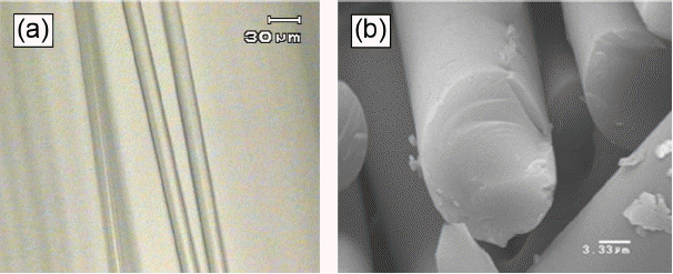
Figue 3 shows the optical microscope and SEM image of the PCS fiber, which is prepared by melt spun process. The PCS fiber has a smooth surface and shows round shape cross-section. And the diameter of the PCS fiber was measured between 15 ~ 20 μm. The green PCS fiber was fabricated by melting and extruding of PCS precursor through the nozzle of spinning unit, that is to say, the extruded molten PCS is cooled and hardened with round shape. This procedure is called the melt spinning process in fiber industry. It is critical that to control the spinning temperature during the process. In the case of low spinning temperature, the PCS fiber does not elongate through the nozzle, and it results in the poor formation of fiber shape. While the temperature of molten PCS is high, the PCS fiber becomes spherical droplet and flow through the nozzle. We fabricated PCS fiber with a smooth surface and round cross-section successfully by control on the viscosity of molten PSC.
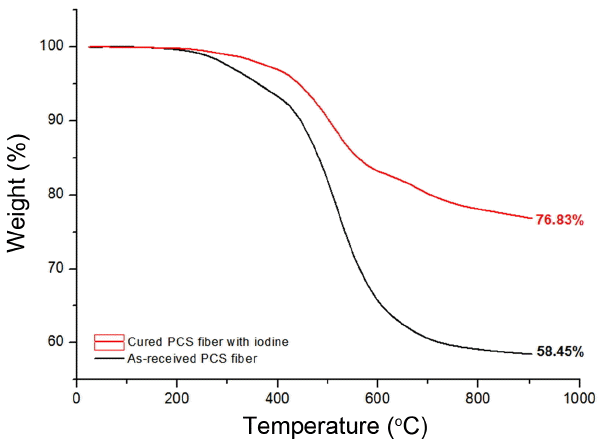
We conducted to pyrolyze the un-cured and cured PCS fibers with iodine vapor using thermogravimetric analysis (TG) to observe the effect of iodine curing for PCS fiber. Fig. 4 indicates the thermogravimetric curves of un-cured and cured PCS fibers with iodine vapor. The pyrolysis yield of un-cured PCS fiber is 58.45wt%. On the other hand, the pyrolysis yield of cured PCS fiber is 75.77wt%. Otherwise, the pyrolysis yield of the PCS fiber was increased 17wt% by iodine vapor curing process. The green PCS fiber is easily softened or melted to result in losing round shape due to its thermoplastic property at high temperature. For prevent losing its round shape, PCS fiber needed to cure for conversion from thermoplastic to thermosetting based on the cross-linking reaction between PCS and iodine molecules.16-18) As shown in Fig. 4, cured PCS fiber shows larger improvement on weight loss, it is a clear proof for the conversion of thermosetting on PCS fiber.
Figure 5 shows PCS fibers(a), cured PCS fibers(b), stacked PCS fibers(c), and fabricated SiC fibers(d) as an according to process flow. White PCS fibers were changed into dark yellow PCS fibers by iodine curing process, which proves a good degree of curing on PCS. And Fig. 5(d) indicates the shrinkage of SiC fiber mat by approximately 30% in size after the pyrolysis, which results the cured PCS fiber mat is achieved in high densification, effectively.
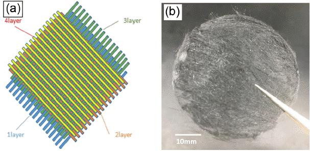
Figure 6. shows the building structure (a) and photograph (b) of SiC fiber mat layers after the pyrolysis. In order to arrange SiC fiber in the layer to layer, we stacked four layers of SiC fiber filaments (Fig. 6. (a)). After the pyrolysis, we successfully obtained a well arranged SiC fiber mat as shown in Fig. 6(b).
Figure 7 indicates SEM images of fabricated SiC fiber mat; (a) surface of mat, (b) side view of mat, (c) side view of SiC fiber filaments and (d) cross section of filaments. Fig. 7(a) and (b) confirmed that SiC fiber is arranged well in one direction on the surface of mat and side view of the mat. SiC fiber filaments, as shown Fig. 7(c) and (d) proved that the necking between SiC fiber filaments leads a force to keep round shape SiC fiber mat. The softening behavior of PCS fiber strongly depends on the degree of curing on PCS fiber. The purpose of accelerating on necking between SiC fiber filaments, we designed graphite mold that upper graphite mold slightly presses the fibers from the top. As a result of the experiment, we obtained successfully the round SiC fiber mat arranged well with few number of necking between SiC fiber filaments.
Figure 8 shows thermal image and temperature curves of SiC fiber mat under microwave (2.45 GHz). The temperature of SiC fiber mat elevated up to maximum 1107°C in 30s with the heating rate of 2214°C/min. Besides, the temperature deviation of SiC fiber mat is 87°C. SiC fiber mat shows the high heating rate under the microwave and stable temperature zone after reaching the maximum temperature. In generally, SiC materials show the dielectric constant in the range of 8 ~ 12 C2/N.m2. Hence, SiC materials can absorb microwave, but its dielectric constant is smaller than that of dielectric materials like BaTiO3, Fe2O3, etc., even though SiC fiber mat was exposed under the microwave. In the case of SiC fiber, it is not enough to emit the heat up to around 1100°C by absorbed microwave due to its lower value of dielectric constant according to conventional theories. However, SiC fiber can be emitted the temperature around above-mentioned under the microwave. It proves that primary reason for emitting such a high temperature is not related to its dielectric constant.
The early literature reported about eddy current in the metal; a microwave can cause the eddy current in SiC fiber. And can be the driving force to emit heat which is called “electric resistance heat,”.19,20) As shown in Fig. 8, the SiC fiber mat emits heat with a homogeneous distribution of temperature under the microwave. That is because SiC fiber mat was arranged as one way and layer by layer. The interaction between microwave and SiC fiber is partially contacted due to the length of microwave (16.4 cm).
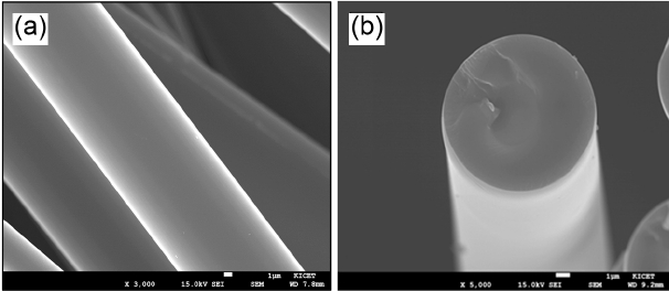
Figure 9 shows SEM images of SiC fiber filament after the emitting heat up to around 1100°C under microwave; (a) side views and (b) cross-section of SiC fiber. SiC fibers were not melted and oxidized after the emitting heat in the microwave. SiC fiber is representative high-temperature resistance material because of its high melting point (over 1800°C), even though it can be oxidized in the air.21) However, its oxidation rate is very low with thin SiO2 layer appeared on the surface of SiC fiber. Oxygen cannot diffuse into SiC fiber core due to the obstruction of the SiO2 layer of the fiber.
4. Conclusions
High-performance silicon carbide fiber mat was successfully obtained from polycarbosilane with the presence of iodine vapor at low pressure condition. Optimization of curing pressure used for curing and heat treatment temperature of SiC fiber can play the leading role for heat radiation efficiency under microwave, according to the results of thermal analysis. The highest temperature on the SiC mat surface is 1107.32°C, and temperature distribution is uniformed, spatially. SiC fiber mat can be used without the difficulty of oxidation under the microwave heating.


